


70
ICC
• Assembly instances 100 and 150: if a register entry in the consumed data
configuration array is 0, then any consumed data that corresponds to that
location will be ignored. Conversely, if a register entry in the produced data
configuration array is 0, then any produced data that corresponds to that location
will be a default value of 0. Refer to section 10.8.4 for further information on the
data configuration arrays.
• Class 1 implicit I/O supports both multicast and point-to-point (unicast) when
producing data in the T→O direction.
• Point-to-point class 1 connected messages will be produced targeting the IP
address of the device that instantiated the connection, UDP port 0x08AE (UDP
port 2222).
• If a class 1 point-to-point connection is established in the (T→O) direction, no
more class 1 connections can be established.
• If a class 1 connection’s consuming half (O→T) times out, then the producing
half (T→O) will also time-out and will stop producing.
• If a class 1 or class 3 connection timeout occurs, the driver will trigger a timeout
event as described in section 10.7.5. The timeout value is dictated by the
scanner/client and is at a minimum, four times the scan rate (Requested Packet
Interval) for class 1. The typical timeout value for class 3 messaging is usually
much larger and is also dictated by the scanner/client.
13.2.2 ODVA AC/DC Drive Profile
The interface card supports the ODVA AC/DC drive profile. No special Ethernet/IP
configuration of the interface card is required when using the AC/DC drive profile: all
that is needed is that the controller must target either assembly instances 20 & 70 or
21 & 71 in its connection parameters.
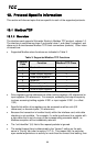
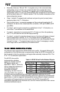
The AC/DC drive profile
implementation provides
support for several required
CIP objects, which are
specified in Table 4. While the
various supported attributes of
all of these objects are
accessible via explicit
messaging, the main intent of
using the AC/DC drive profile is
to interact with the predefined input and output assembly instances via an I/O
connection. The structure of these assembly instances is defined by the Ethernet/IP
specification in order to engender interoperability among different vendor’s products.
This section will focus primarily on the format of the AC/DC drive profile I/O
assemblies supported by the interface card, and the inverter data which their various
constituent elements map to.
Table 4: AC/DC Drive Profile-Related Objects
Class Code Object Name
0x04 Assembly Object
0x28 Motor Data Object
0x29 Control Supervisor Object
0x2A AC Drive Object