


78
ICC
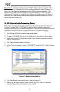
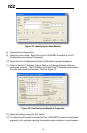
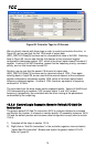
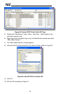
Figure 82: Controller Tags for I/O Access
We can directly interact with these tags in order to control and monitor the drive. In
Figure 82, we can see that the first 16-bit word of output data
(ASD_G9ETH:O.Data[0]) has been set to a hexadecimal value of 0xC400. Referring
back to Figure 36, we can see that the first element of the consumed register
configuration references register 1007, which is the drive’s option board Command 1
register. A value of 0xC400, therefore, means that the frequency priority, command
priority, and run bits have been turned ON.
Similarly, we can see that the second 16-bit word of output data
(ASD_G9ETH:O.Data[1]) has been set to a decimal value of 1234. Once again
referring back to Figure 36, we can see that the second element of the consumed
register configuration references register 1008, which is the drive’s option board
frequency command register. A value of 1234, therefore, equates to a frequency
command of 12.34Hz.
The input data from the drive shows similar expected results. Values of 0x6404 and
1234 corresponding to registers 1402 (inverter status 1) and 1401 (output
frequency), respectively, are consistent with the drive running at the parameters
commanded by the output tag.
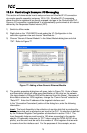
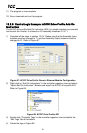
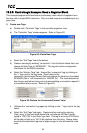
13.2.5 ControlLogix Example: Generic Default I/O Add-On
Instruction
The generic default I/O Add-On Instruction (AOI) is a simple interface to command
and monitor the inverter. It is based on vendor-specific I/O assembly instances 100 &
150 and the default produce and consume data configuration arrays (refer to section
10.8.4).
1) Complete all the steps in section 13.2.4.
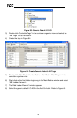
2) Right click on “Add-On Instructions” in the controller organizer view and select
“Import Add-On Instruction”. Browse and import the generic default I/O AOI.
Refer to Figure 83.