


92
ICC
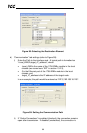
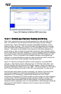
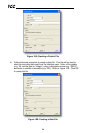
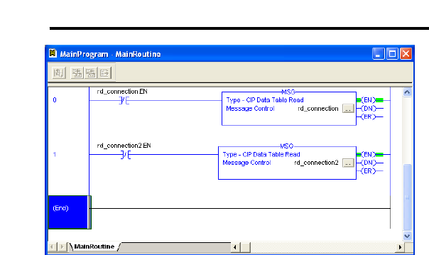
Figure 105: Reading Via Multiple MSG Instructions
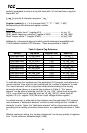
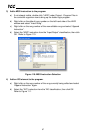
13.2.11 ControlLogix Example: Reading and Writing
Often times, applications may need to both read data from and write data to the
drive. At a minimum, this will require two MSG instructions and two message
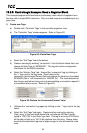
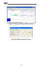
controller tags. Figure 106 shows an example of two MSG instructions, one for
reading and one for writing. The only item of note that differentiates this example
from the multiple-read example in section 13.2.10 is the addition of the en_wr XIC
element. The reason for the addition of this element is that while reading from a
remote device is often continuously performed (monitoring), data is typically written
to the remote device only when necessary (i.e. when the value to write has changed).
This conserves both network bandwidth and potentially EEPROM lifespans on the
target device. The en_wr element in this example, therefore, would typically be
replaced in an actual application program by user-provided logic which controls the
conditions under which a write operation would be performed.
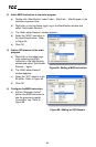
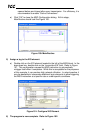
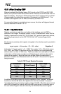
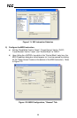
Figure 107 shows the configuration details of the example wr_connection MSG
instruction. Note that the chosen “Message Type” is “CIP Data Table Write”, and
that this instruction will only be writing to one drive register: namely, the frequency
command (Destination Element is wr_reg_1008). The Source Element in this case is
the 8
th
element (starting from index 0) of an INT array tag named “wr_data_array”.
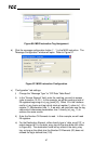
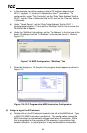
Note that when writing data via explicit messaging, use caution to ensure that the
commanded registers are not also simultaneously being commanded in the
background via I/O messaging. Indeterminate behavior can occur if MSG
instructions and background I/O data transfers are both writing to the same registers.
In other words, if the I/O messaging example procedure detailed in section 13.2.4
has already been implemented, and the same program is now being modified to
implement explicit messaging, then it is recommended to inhibit the target module by
selecting the “Inhibit Module” checkbox in the Connection tab of the Module
Properties dialog.