


100
ICC
additional logic elements to allow triggering the MSG instruction at a specific
rate or under specific conditions.
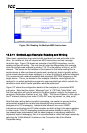
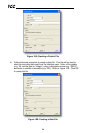
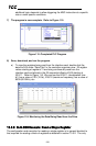
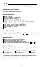
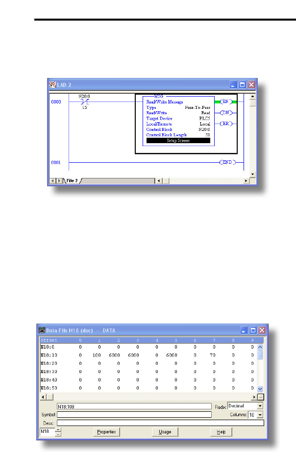
7) The program is now complete. Refer to Figure 115.
Figure 115: Completed PLC Program
8) Save, download, and run the program.
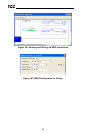
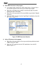
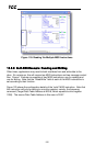
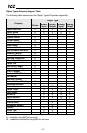
a) To view the registers being read from the interface card, double-click the
data file N18 under “Data Files” in the controller organizer view. 25 register
values starting at register #11 are being continuously read from the
interface card and placed in the 25 sequential offsets of N18 starting at
N18:11. Refer to Figure 116. We can see that N18:11 (deceleration time
#1) has a value of 100 (10.0s), N18:12 (maximum frequency) has a value of
6000 (60.00Hz), etc.
Figure 116: Monitoring the Data Being Read from the Drive
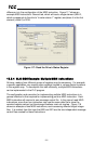
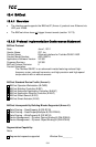
13.3.3 SLC-5/05 Example: Read a Single Register
The configuration and execution for reading a single register is in general identical to
that required for reading a block of registers as detailed in section 13.3.2. The only