


14
ICC
5. Installation
This interface card has been designed for quick and simple installation. The card is
connected to the drive's control board via a 30-pin rectangular connector, and is
mechanically supported via an integral housing that seamlessly mates with the
drive’s enclosure. The only tool required for installation is a flat-blade screwdriver.
Before opening the drive, please observe all safety precautions as outlined on the
drive's front cover and in the operation manual.
5.1 Installation Procedure
1. CAUTION! Verify that all input power sources to the drive have
been turned OFF and are locked and tagged out.
2. DANGER! Wait at least 5 minutes for the drive’s electrolytic
capacitors to discharge before proceeding to the next step. Do not touch any
internal parts with power applied to the drive, or for at least 5 minutes
after power to the drive has been removed. A hazard exists temporarily for
electrical shock even if the source power has been removed. Verify that the
CHARGE LED has gone out before continuing the installation process.
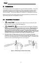
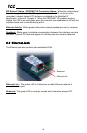
3. Remove the drive’s display panel and front cover by inserting a flat-blade
screwdriver into each of the two mounting tab access openings at the top of the
front cover and depressing each of the mounting tabs (Figure 1). Rotate the top
of the font cover outward and remove the cover (Figure 2).
Figure 1: Releasing the Drive's Front Cover