


77
ICC
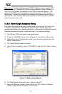
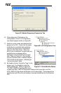
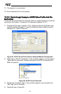
Figure 79: Module Properties Connection Tab
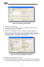
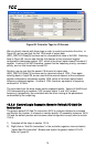
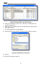
6) After adding the I/O Module to the
configuration, the full I/O Configuration
tree should appear similar to Figure 80.
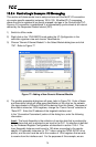
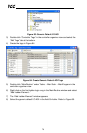
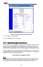
7) Switch to online mode and download the
project to the PLC. Verify that the newly-
added drive is available and operating
correctly by observing any indications
shown on the drive’s icon. When the
drive’s icon is selected, its status and any
available error messages will be
displayed in the area below the project
tree. Refer to Figure 81. Also confirm
that the interface card’s “Network Status”
LED should be solid green, indicating an
“online/connected” state.
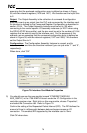
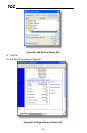
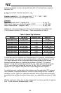
8) By double-clicking “Controller Tags” in the
project tree, it is possible to view the
newly-added tags. Refer to Figure 82.
The ASD_G9ETH:C configuration tag is
unused, the ASD_G9ETH:I tag allows viewing of the input data, and the
ASD_G9ETH:O tag allows modification of the output data. These tags will be
synchronized with the drive at whatever rate was established for the module’s
RPI.
Figure 80: I/O Configuration Tree
Figure 81: Online Module Status