


41
ICC
configurable, and is utilized when the client opens a connection to the interface using
assembly instances 100 and 150.
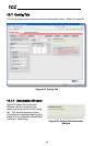
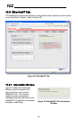
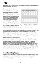
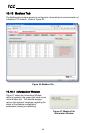
The user-configurable data arrays
consist of two separate elements (refer
to Figure 36.) The consumed register
configuration defines the structure of
the command data sent from the
EtherNet/IP controller (for example, a
ControlLogix PLC) to the drive, and the
produced register configuration defines
the structure of the status data sent
from the drive back to the controller.
These arrays allow the creation of
custom-built I/O data. Up to 32
command registers can be sent to the
drive, and up to 32 status registers can
be sent back to the controller. Each
box in an array is capable of containing
a register number. Because all drive
registers are 16-bit data elements,
each box therefore represents two bytes of consumed or produced data.
Each of the register array locations are numbered 0-31, and traverse from left to right
across each row, and then increment to the left-most position on the next row.
Clicking on a box in an array allows the user to enter a register number that will be
referenced at that location when data is either consumed from the controller or
produced to the network. A value of 0 indicates that no register is referenced at that
location, which will cause the corresponding consumed data to be ignored and
produced data to be a default value of 0.
As an example, looking at the default configuration shown in Figure 36, we can see
that each array contains two defined registers. Therefore, up to 4 “meaningful” bytes
of data can be both received and sent (the qualifier “meaningful” is used here
because the connection sizes configured in the controller may request larger
consumed and/or produced data sizes, but all unreferenced consumed data will be
ignored, and all unreferenced produced data will contain dummy “0” values). The
first word (two bytes) of consumed data will be written to register 1007 (command 1)
and the second word will be written to register 1008 (frequency command). Similarly,
the first word of produced data will contain the value of register 1402 (status 1) and
the second word will contain the value of register 1401 (output frequency).
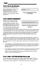
10.8.5 Submitting Changes
Whenever any of the EtherNet/IP configuration elements (Device Name or I/O array
configurations) have been changed, the “submit” button located in the right-hand
portion of the web page must be clicked in order to write these settings to the
interface card’s filesystem.
Figure 36: EtherNet/IP Class 1 (I/O) Data
Configuration