


40
ICC
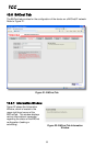
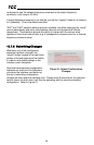
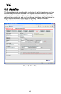
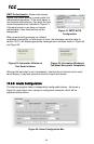
10.8.2 Device Identification
A text entry box is available which
allows customization of the device’s
name for identification on the
EtherNet/IP network. This string is
accessible as the “product name”
attribute of the identity object. Refer
to Figure 34.
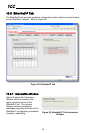
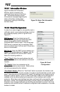
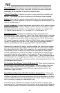
10.8.3 Run/Idle Flag Behavior
EtherNet/IP clients (such as PLCs)
have the option of adding a 32-bit
“run/idle” header to all class 1 (I/O)
data packets sent to devices. Bit 0 of
this header is called the “run/idle flag”
by the EtherNet/IP specification, and
is intended to signify when the client is
in a “running” state or an “idle” state.
A running state (run/idle flag = Run) is indicated whenever the client is performing its
normal processing (e.g. scanning its ladder logic). An idle state (run/idle flag = Idle)
is indicated otherwise. For example, Allen Bradley ControlLogix PLCs will set their
run/idle flag to Idle whenever their processor keyswitch is placed in the “PROG”
position, presumably in preparation to receive a new application program from
RSLogix.
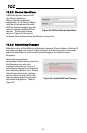
The behavior of EtherNet/IP devices when they receive I/O data from a controller
with the run/idle flag set to Idle is not specified in the EtherNet/IP specification. The
interface card allows the option of two different behavioral responses when a run/idle
flag = Idle condition is received, depending on the state of the checkbox indicated in
Figure 35.
• If the checkbox is cleared (default setting), then the interface card will maintain
the last I/O data values received from the client. For example, if the inverter was
being commanded to run prior to the run/idle flag being set to Idle, then it will
continue to run.
• If the checkbox is checked, then the interface card will invoke its user-configured
timeout processing (refer to section 10.7.5). This setting allows the user to
determine any inverter behavior they may desire (stop the inverter, fault the
inverter, ramp to a preset speed, etc.)
10.8.4 Class 1 (I/O) Data Configuration Arrays
The interface card supports two different types of EtherNet/IP class 1 (I/O) data
transfer. One type is included with the implementation of the AC/DC drive profile,
and requires no user configuration. The other type, however, is entirely user-
Figure 34: EtherNet/IP Device
Identification
Figure 35: Run/Idle Flag Behavior
Selection