


76
ICC
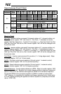
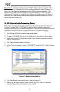
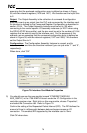
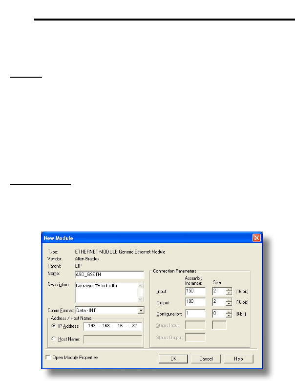
assuming that the produced configuration array is defined as shown in Figure
36, with two relevant registers (1402 and 1401). We therefore set the Input Size
to 2.
Output: The Output Assembly is the collection of command & configuration
data that is sent as an output from the PLC and consumed by the interface card.
Its structure is defined by the Consumed Register Configuration as described in
section 10.8.4. The Output Assembly Instance must be set to 100 when
connecting to the vendor-specific I/O assembly instances (or 20/21 when using
the ODVA AC/DC drive profile), and the size must be set to the number of 16-bit
registers that we wish to send to the interface card. For the purposes of this
example, we are assuming that the consumed configuration array is defined as
shown in Figure 36, with two relevant registers (1007 and 1008). We therefore
set the Output Size to 2.
Configuration: The Configuration Assembly Instance is unused, and its
instance number and size are therefore irrelevant (you can just enter “1” and “0”,
respectively).
When done, click “OK”.
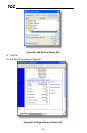
Figure 78: Interface Card Module Properties
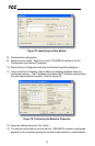
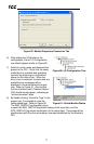
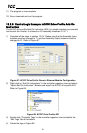
5) You should now see the new module (named “ETHERNET-MODULE
ASD_G9ETH”) in the 1756-ENBT/A branch under the I/O Configuration in the
controller organizer view. Right click on this new module, choose “Properties”,
and select the Connection tab. Refer to Figure 79.
Confirm the setting of the Requested Packet Interval (RPI). The RPI defines the
amount of time (in milliseconds) between data exchanges across an I/O
connection. The smallest RPI supported by the interface card is 10ms.
Click OK when done.