


37
ICC
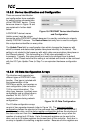
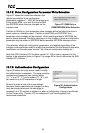
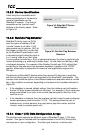
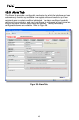
10.7.4 IP Address Configuration
Figure 29 shows the configuration items used to
modify the IP address-related parameters.
Modification of these settings is consistent with
the technique used with the Finder utility (refer
to section 7.1). Figure 29 also shows the text
entry boxes that are used to view and/or modify
the unique MAC address of the interface card.
The MAC address should not be changed
without first consulting ICC Technical Support.
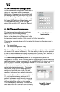
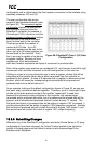
10.7.5 Timeout Configuration
The interface can be configured to perform a
specific set of actions when network
communications are lost. Support for this
feature varies depending on the protocol: refer
to the protocol-specific section of this manual for further information.
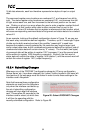
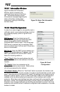
There are two separate elements that comprise the timeout configuration (refer to
Figure 30):
• The timeout time
• The timeout configuration array
The timeout time is a floating-point number which allows adjustment down to 1/100
th
of a second (0.01 second increments). This time setting is used by certain protocols
in order to determine abnormal loss-of-communications conditions and, optionally, to
trigger a timeout processing event. The default timeout time is 10s.
The timeout configuration array allows up to 10 register/value pairs to be
designated by the user. When a timeout event is triggered by a protocol, the timeout
configuration array indexes are parsed. If the “register” field for an index is set to 0,
then this index is “disabled” and therefore ignored. If, on the other hand, the
“register” field is non-zero, then the value
contained in the “value” field is automatically
written to the designated register. This flexible
mechanism allows up to 10 designated drive
registers to have their own unique “fail-safe”
conditions in the event of a network interruption.
For example, Figure 30 shows a timeout time of
10s, and one timeout entry assignment. If a
protocol that makes use of timeout processing
triggers a timeout event, then a value of 5000
will automatically be written to drive register
1008 (the frequency command). Provided the
drive has a valid “run” command and is currently
Figure 29: IP Address
Configuration
Figure 30: Timeout
Configuration