


87
ICC
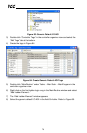
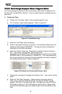
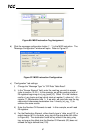
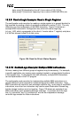
Figure 96: MSG Instruction Tag Assignment
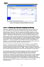
b) Click the message configuration button (“…”) in the MSG instruction. The
“Message Configuration” window will open. Refer to Figure 97.
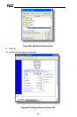
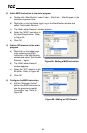
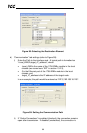
Figure 97: MSG Instruction Configuration
c) “Configuration” tab settings:
i) Change the “Message Type” to “CIP Data Table Read”.
ii) In the "Source Element” field, enter the read tag you wish to access
(refer to section 13.2.5.) In this example, we will be reading a total of
25 registers beginning at rd_reg_basic[10]. Offset 10 in the interface
card’s rd_reg_basic root tag (which starts at register 1) refers to 1+10 =
register 11 (deceleration time 1). If we wish, we could also use the tag
name which references deceleration time 1 directly (rd_reg_11) to
achieve the same results.
iii) Enter the Number Of Elements to read. In this example, we will read
25 registers.
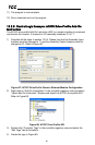
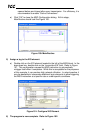
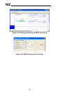
iv) For the Destination Element, either directly type in “data_array[10]”, or
select element #10 in the data_array tag via the drop-down box (refer
to Figure 98). The destination could be any offset in the data_array
tag, as long as the offset plus the Number Of Elements (25) does not
exceed the tag’s defined size (100).