


66
ICC
13. Protocol-Specific Information
This section will discuss topics that are specific to each of the supported protocols.
13.1 Modbus/TCP
13.1.1 Overview
The interface card supports Schneider Electric’s Modbus TCP protocol, release 1.0.
The interface is conformance class 0 and partial class 1 and class 2 compliant, and
allows up to 8 simultaneous Modbus TCP client connections (sockets). Other notes
of interest are:
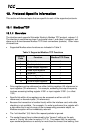
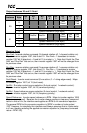
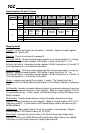
• Supported Modbus slave functions are indicated in Table 3.
Table 3: Supported Modbus TCP Functions
Function
Code
Function Modbus TCP Class
1 Read coils 1
2 Read input status 1
3 Read multiple registers 0
4 Read input registers 1
5 Write coil 1
6 Write single register 1
15 Force multiple coils 2
16 Write multiple registers 0
• Drive registers can be addressed as either holding registers (4X references) or
input registers (3X references). For example, accessing the output frequency
involves accessing holding register 41301 or input register 31301 (i.e. offset
1301).
• Specific bits within drive registers can be accessed as either coils (0X
references) or discrete inputs (1X references).
• Because the transaction is handled locally within the interface card, write data
checking is not available. For example, if a write is performed to a register with
a data value that is out-of-range of the corresponding parameter object, no
Modbus exception will be immediately returned.
• The “unit identifier” (UI) field of the request packets is ignored.
• The socket timeout time is determined by the “timeout” setting on the web
server’s “Config” tab (refer to section 10.7.5). This means that if a particular
open socket experiences no activity for more than the timeout time setting, then