


67
ICC
the interface assumes that the client or network has experienced some sort of
unexpected problem, and will close that socket.
• Because the socket timeout determination is performed on a per-socket basis,
note that a certain degree of caution must be exercised when using the network
timeout feature to avoid “nuisance” timeouts from occurring. Specifically, do not
perform inadvisable behavior such as sending a request from the master device
to the interface, and then closing the socket prior to successfully receiving the
unit’s response. The reason for this is because the interface will then
experience an error when attempting to respond via the now-closed socket,
which will immediately trigger the timeout action. Always be sure to manage
socket life cycles “gracefully”, and do not abandon outstanding requests.
• If a socket timeout occurs (regardless of whether it was due to a communication
lapse or abnormal socket error), the driver will trigger a timeout event as
described in section 10.7.5.
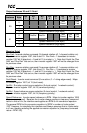
13.1.2 Coil & Discrete Input Mappings
The Modbus TCP driver provides read/write support for coils (0X references) and
read-only support for discrete inputs (1X references). These will collectively be
referred to from here on out as simply “discretes”. Accessing discretes does not
reference any new physical data: discretes are simply indexes into various bits of
existing registers. What this means is that when a discrete is accessed, that discrete
is resolved by the interface into a specific register, and a specific bit within that
register. The pattern of discrete-to-register/bit relationships can be described as
follows:
Discrete 1...16 map to register #1, bit0...bit15 (bit0=LSB, bit15=MSB)
Discrete 17...32 map to register #2, bit0...bit15, and so on.
Arithmetically, the discrete-to-register/bit relationship can be described as follows:
For any given discrete, the register in which that discrete resides can be determined
by:
⎥
⎦
⎥
⎢
⎣
⎢
+
=
16
15discrete
register
Equation 1
Where the bracket symbols “
⎣ ⎦” indicate the “floor” function, which means that any
fractional result (or “remainder”) is to be discarded, with only the integer value being
retained.
Also, for any given discrete, the targeted bit in the register in which that discrete
resides can be determined by:
161discretebit %)(
−
=
Equation 2
Where “discrete” ∈[1…65535], “bit” ∈[0…15], and “%” is the modulus operator, which
means that any fractional result (or “remainder”) is to be retained, with the integer
value being discarded (i.e. it is the opposite of the “floor” function).