


101
ICC
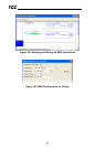
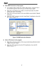
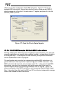
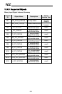
difference is in the configuration of the MSG instruction. Figure 117 shows an
example MSG instruction’s General tab, which will read a single element (N24:2,
which corresponds to the drive’s “inverter status 1” register) and place it in the first
element (offset 0) of N18.
Figure 117: Read the Drive’s Status Register
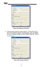
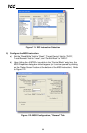
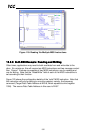
13.3.4 SLC-5/05 Example: Multiple MSG Instructions
At times, reading from different groups of registers may be necessary. For example,
a specific application may require some registers located in various disjoint locations
in the register map. To accomplish this task efficiently, multiple MSG instructions
can be implemented in the PLC program.
The configuration and execution for implementing multiple MSG instructions is in
general identical to that required for implementing just one MSG instruction. Each
MSG instruction will require its own message control file. In the case of read MSG
instructions, more than one instruction may use the same data file to store the
received register values, but the storage locations must not overlap. Figure 118
shows an example of two MSG instructions, each accessing different target integer
files. It is evident from this logic that N20 and N21 are the two independent message
control files created for these instructions.