


95
ICC
configuration array (refer to section 10.8.4). Similarly, when N50 is targeted for
writing, the written data is disseminated to the drive’s registers according to the
definition contained in the EtherNet/IP consumed register configuration array. By
appropriate configuration of the EtherNet/IP consumed and produced register
configuration arrays, therefore, bulk access to non-contiguous but frequently-used
drive registers can be conveniently provided by performing only one read and/or write
instruction targeting file N50.
Because both the EtherNet/IP consumed and produced register configuration arrays
are comprised of 32 register definitions, the targeted “offset/element” must be within
the range of 0 to 31 inclusive. Refer to Table 7 for some examples of N50 accesses.
Table 7: Examples of EtherNet/IP-Style Bulk Access via File N50
Offset/Element
Start Target Register of
Configuration Array
Max Number of
Accessible Elements
0 1st 32
: : :
15 16th 16
: : :
31 32nd 1
The application PLC program uses a MSG instruction that is configured with a “Data
Table Address” from which to start the access and a “Size in Elements” which
determines the number of items to access (read or write). The “Data Table Address”
is constructed by selecting a “File/Section Number” and an “Offset/Element”
according to Equation 3. For example, a “File/Section Number” of N23 and
“Offset/Element” of 5 = N23:5, which corresponds to register 1305 (the drive’s input
voltage monitor register).
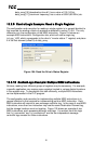
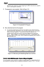
13.3.2 SLC-5/05 Example: Read a Register Block
This example program will show how to continuously read a block of registers from
the drive with a single MSG instruction. Only one read request is outstanding at any
given time.
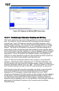
1) Run RSLogix 500, and create a new configuration.
2) Create a control and a data file.
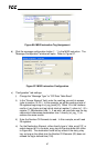
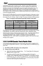
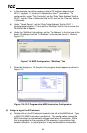
a) Right click Data Files and select New… The “Create Data File” dialog box
appears (refer to Figure 108).
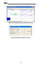
b) To create a control file, enter a file number (e.g. 20), set the type to
“Integer”, enter a descriptive name (e.g. “CONTROL”), and enter a number
of elements (e.g. 100). Click OK to create the file. The control file is used
to store configuration information pertaining to the functionality of the MSG
instruction which will perform the data read.