


W7 ASD Installation and Operation Manual 13
Installation and Connections
The W7 Adjustable Speed Drive may be set up initially by performing a few simple configuration
settings. To operate properly, the ASD must be securely mounted and connected to a power source (3-
phase AC input at the L1/R, L2/S, and L3/T terminals). The control terminals of the ASD may be used
by connecting the terminals of the Control Terminal Strip to the proper sensors or signal input sources
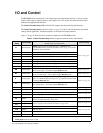
(see the section titled
I/O and Control on pg. 17).
The output terminals of the ASD (T1/U, T2/V, and T3/W) must be connected to the motor that is to be
controlled (see
Figure 17 on pg. 24).
As a minimum, the installation of the ASD shall conform to Article 110 of the 2005 NEC, the
Occupational Safety and Health Administration requirements, and to any other local and regional
industry codes and standards.
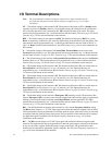
Installation Notes
When a brake-equipped motor is connected to the ASD, it is possible that the brake may not release at
startup because of insufficient voltage. To avoid this, Do Not connect the brake or the brake contactor to
the output of the ASD.
If an output contactor is used for bypass operation, it must be interlocked such that commercial power is
never applied to the output terminals of the ASD (T1/U, T2/V, or T3/W).
If a secondary magnetic contactor (MC) is used between the output of the ASD and the motor, it should
be interlocked such that the ST – CC connection is disconnected before the output contactor is opened.
Do Not open and then close a secondary magnetic contactor between the ASD and the motor unless the
ASD is off and the motor is not rotating.
Note: Re-application of power via a secondary contact while the ASD is on or while the
motor is still turning may cause ASD damage.
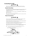
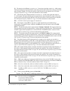
On some devices the ST-to-CC connection is further enhanced by the operation of the MS1 AUX relay
circuit. The MS1 AUX relay circuit is normally open and closes the ST-to-CC connection (via ST1)
only after normal system power is available. The MS1 AUX relay circuit prohibits the ST-to-CC
connection in the event that the MS1 contactor fails to close during start up or if MS1 opens while the
ASD is running. For the 460 volt ASD this feature is available on the 75 HP and above systems.
Figure 2. Alternative ST activation using the MS1 AUX circuit configuration.
The ASD input voltage should remain within 10% of the specified input voltage range. Input voltages
approaching the upper or lower limit settings may require that the overvoltage and undervoltage stall
protection level parameters be adjusted. Voltages outside of the permissible tolerance should be
avoided.
The frequency of the input power should be ±2 Hz of the specified input frequency.
Do not use an ASD with a motor that has a power rating that is higher than the rated output of the ASD.