


W7 ASD Installation and Operation Manual 17
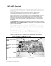
Control Terminal Strip
I/O and Control
The W7 ASD can be controlled by several input types and combinations thereof, as well as operate
within a wide range of output frequency and voltage levels. This section describes the ASD control
methods and supported I/O functions.
The Control Terminal Strip PCBA (P/N 48570) supports discrete and analog I/O functions.
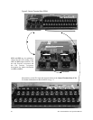
The Control Terminal Strip is shown in Figure 5 on pg. 20. Table 2 and lists the names, the default
settings (where applicable), and the descriptions of the input and output terminals.
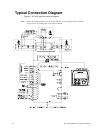
Figure 17 on pg. 24 shows the basic connection diagram for the W7 ASD system.
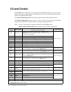
Table 2. Control Terminal Strip default assignment terminal names and functions.
Terminal
Name
Input/Output
Terminal Function
(default setting if programmable)
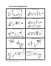
Circuit Config.
ST Discrete Input
Standby (jumper to CC to operate the unit) — Multifunctional
programmable discrete input (see
Installation Notes on pg. 13 for further
information on this terminal).
Figure 7 on pg. 23.
RES Discrete Input
Reset — Multifunctional programmable discrete input.
F Discrete Input
Forward — Multifunctional programmable discrete input.
R Discrete Input
Reverse — Multifunctional programmable discrete input.
S1 Discrete Input
Preset Speed 1 — Multifunctional programmable discrete input.
S2 Discrete Input
Preset Speed 2 — Multifunctional programmable discrete input.
S3 Discrete Input
Preset Speed 3 — Multifunctional programmable discrete input.
S4 Discrete Input
Emergency Off — Multifunctional programmable discrete input.
RR Analog Input
RR — Multifunction programmable analog input
(0.0 to 10 volt input — 0 to 80 Hz output). Reference CC.
Figure 8 on pg. 23.
RX Analog Input
RX — Multifunctional programmable analog input
(-10 to +10 VDC input — -80 to +80 Hz output). Reference CC.
Figure 9 on pg. 23.
II Analog Input
II — Multifunctional programmable analog input (4 [0] to 20 mADC
input — 0 to 80 Hz output) (see
Figure 5 on pg. 20 for the location of the
II terminal). Reference CC.
Figure 10 on pg. 23.
VI Analog Input
VI — Multifunctional programmable analog input
(0 to 10 VDC input — 0 to 80 Hz output). Reference CC.
P24
DC Output
24 VDC @ 50 mA output.
Figure 11 on pg. 23.
PP
DC Output
PP — 10.0 VDC voltage source for the external potentiometer.
Figure 12 on pg. 23.
OUT1
Discrete Output
Low Frequency — Multifunctional programmable discrete output.
Figure 13 on pg. 23.
OUT2
Discrete Output
Reach Frequency — Multifunctional programmable discrete output.
FP Output
Frequency Pulse — an output pulse train that has a frequency which is
based on the output frequency of the ASD.
Figure 14 on pg. 23.
AM
Output
Produces an output current that is proportional to the magnitude of the
function assigned to this terminal (see
Table 8 on page 142).
Figure 15 on pg. 23
FM
Output
FLC
Output
Fault relay (common).
Figure 16 on pg. 23.
FLB
Output
Fault relay (N.C.).
FLA
Output
Fault relay (N.O.).
CC
—
Control common (Do Not connect to Earth Gnd).
Discrete Input Terminals On = connected to CC.
Analog Input terminals reference CC.