


W7 ASD Installation and Operation Manual 19
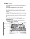
II — The function of the II input is to receive a 4 – 20 mA input signal that controls a 0 – 80 Hz output.
This input terminal may be programmed to control the speed or torque of the motor and may not be used
when using the VI input. Also, the gain and bias of this terminal may be adjusted. See
VI/II Speed
Frequency Setpoint #1 on pg. 134 for more information on this terminal.
VI — The function of the VI input terminal is to receive a 0 – 10 VDC input signal that controls a
0 – 80 Hz output. This input terminal may be programmed to control the speed or torque of the motor
and may not be used when using the II input. Also, the gain and bias of this terminal may be adjusted.
See
VI/II Speed Frequency Setpoint #1 on pg. 134 for more information on this terminal.
P24 — +24 VDC @ 50 mA power supply for customer use.
PP — The function of output PP is to provide a 10 VDC output that may be divided using a
potentiometer. The tapped voltage is applied to the RR input to provide manual control of the RR
programmed function.
OUT1 — The default setting for this output terminal is Damper Command. This output terminal may
be programmed to provide an indication that 1 of 60 possible events has taken place. This function may
be used to signal external equipment or to activate the brake. The OUT1 contact is rated at 2A/250
VA C. See
OUT1 Terminal on pg. 89 for more information on this terminal.
OUT2 — The default setting for this output terminal is ACC/DEC Complete. This output terminal
may be programmed to provide an indication that 1 of 60 possible events has taken place. This function
may be used to signal external equipment or to activate the brake. The OUT2 contact is rated at 2A/250
VA C. See
OUT2 Terminal on pg. 89 for more information on this terminal.
FP — The default function of this output terminal is to output a series of pulses at a rate that is a
function of the output frequency of the ASD. As the output frequency of the ASD goes up so does the
FP output pulse rate. This terminal may be programmed to provide output pulses at a rate that is a
function of the output frequency or the magnitude of any 1 of the 31 the functions listed in
Table 8 on
page 142. See FP Terminal Assignment on pg. 74 for more information on this terminal.
AM — This output terminal produces an output current that is proportional to the output frequency of
the ASD or of the magnitude of the function assigned to this terminal. The available assignments for
this output terminal are listed in
Table 8 on page 142. See AM Terminal Assignment on pg. 55 for more
information on this terminal.
FM — This output terminal produces an output current that is proportional to the output frequency of
the ASD or of the magnitude of the function assigned to this terminal. The available assignments for
this output terminal are listed in
Table 8 on page 142. See FM Terminal Assignment on pg. 73 for more
information on this terminal.
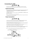
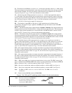
FLC — FLC is the middle leg of a single-pole double-throw (relay) switch. This FLC contact of the
relay is switched between FLB and FLA. This contact may be programmed to switch between FLB and
FLA as a function of any 1 of the 60 conditions listed in
Table 7 on page 141.
FLB — One of two contacts that, under user-defined conditions, connect to FLC (see Figure 4).
FLA — One of two contacts that, under user-defined conditions, connect to FLC (see Figure 4).
Note: The FLA and FLC contacts are rated at 2A/250 VAC. The FLB contact is rated at
1A/250 VAC.
CC — Control common (Do Not connect to Earth Gnd).
Figure 4. FLA, FLB, and FLC switching contacts shown in the de-energized state.
Note: The relay is shown in the Faulted or
de-energized condition. During
normal system operation the relay
connection is FLC-to-FLA.