


W7 ASD Installation and Operation Manual 29
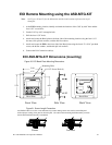
EOI Remote Mounting using the ASD-MTG-KIT
Note: See Figures 20 and 21 for the dimensions and the item locations referenced in steps 1
through 6.
1. At the EOI mounting location, identify and mark the locations of the 5.00” by 4.60” hole and the
four 11/32” screw holes.
2. Cut the 5.00” by 4.60” rectangular hole.
3. Drill the four 11/32” holes.
4. Attach and secure the Bezel plate to the front side of the mounting location using the four 10-32
hex nuts, #10 split lock washers, and the #10 flat washers.
5. Attach and secure the EOI to the front side of the Bezel plate using the four 6-32 x 5/16” pan head
screws, the #6 flat washers, and the #6 split lock washers.
6. Connect the RJ-45 extension cable(s).
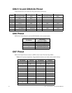
EOI ASD-MTG-KIT Dimensions (mounting)
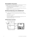
Figure 20. EOI Bezel Plate Mounting Dimensions.
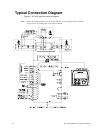
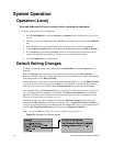
Figure 21. Screw Length Precaution.
Front View Side View Back View
4.60
5.38
4.25
5.00
Bezel Plate Bezel Plate
Mounting Hole
11/32" Screw Hole (4)
C
AUTION: Failure to use the correct hardware may result in damage to the outer surface of the EOI panel
a
nd/or improper seating of the panel to the bezel plate. Use caution when mounting the EOI assembly to ensur
e
t
hat the internal thread clearance is maintained.
Correct Incorrect