


W7 ASD Installation and Operation Manual 15
Connecting the ASD
Refer to the section titled Installation Precautions on pg. 5 and the section titled Lead Length
Specifications on pg. 16 before attempting to connect the ASD and the motor to electrical power.
System Grounding
Proper grounding helps to prevent electrical shock and to reduce electrical noise. The ASD is designed
to be grounded in accordance with Article 250 of the 2005 NEC or Section 10/Part One of the
Canadian Electrical Code (CEC).
The grounding conductor shall be sized in accordance with Article 250-122 of the 2005 NEC or Part
One-Table
6 of the CEC.
Note: The metal of conduit is not an acceptable ground.
The input power, output power, and control lines of the system shall be run in separate metal conduits
and each shall have its own ground conductor.
Power Connections
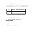
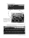
Connect the 3-phase input power to the input terminals of the W7 ASD at L1/R, L2/S, and L3/T.
Connect the output terminals T1/U, T2/V, and T3/W of the W7 ASD to the motor.
The input and output conductors and terminal lugs used shall be in accordance with the specifications
listed in the section titled
Cable/Terminal Specifications on pg. 154.
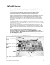
An inductor may be connected across terminals PA and PO to provide additional filtering. When not
used, a jumper must be connected across these terminals (see
Figure 17 on pg. 24).
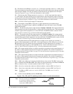
Connect the input and output power lines of the W7 ASD as shown in Figure 3.
Install a molded case circuit breaker (MCCB) or fuse between the 3-phase power source and the W7
ASD in accordance with the fault current setting of the ASD and 2005 NEC Article 430.
Note: In the event that the motor rotates in the wrong direction when powered up, reverse
any two of the three ASD output power leads connected to the motor.
Figure 3. ASD/Motor connection diagram.
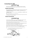
DANGER
DANGER