Installation
2-16 975-0200-01-01
Step 7: Connecting Remote Sensing
Remote sensing permits you to shift the regulation point of the power
supply from the output terminals to the load or other distribution
terminals.
Use shielded twisted pair wiring of 20 to 26 AWG for best noise
performance. Make sure that the shielded twisted pair wiring insulation is
rated higher than the maximum output voltage of the power supply. If
possible, one end of the shield of the sense lines should be attached to the
chassis ground of the power supply.
To connect the remote sense wires:
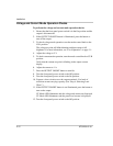
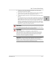
1. Ensure that the front panel power switch is in the Off position.
2. Using a small flat blade screwdriver, remove the two sense jumpers
from pins J1.1 and J1.2, and from pins J1.5 and J1.6 on the APG
Connector. See
Figure 4-1, “APG Connector Terminals” on page 4–5.
WARNING: Shock hazard
There is a potential shock hazard at the sense connectors when using a power
supply at an output greater than 40 V. Select wiring with a minimum insulation
rating equivalent to the maximum output voltage of the power supply for use as
local sense jumpers or for remote sense wires. Ensure that connections at the load
end are shielded to prevent contact with hazardous voltages.
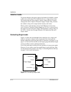
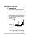
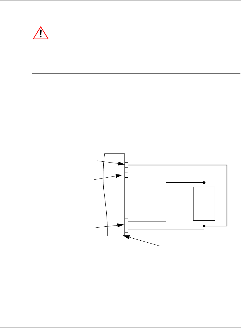
Figure 2-4
Remote Sense Connection
+SNS
-SNS
output +
output -
LOAD
Output terminals on
power supply
Pin J1.1 on APG
connector
Pin J1.6 on APG
connector
Chassis ground stud


