Interlock Function
975-0200-01-01 3-33
3
Interlock Function
The Interlock function can be used to wire an external shutoff switch that
can be used to enable or disable the power supply output. When the
switch is closed the power supply will operate normally. If the switch is
opened, the power supply will trigger the interlock alarm. The output will
be disabled, the display will blink In Loc, and the ALARM LED will
illuminate. This alarm will automatically clear when the switch closes
again and the output will automatically be restored to its pre-alarm state
(either enabled or disabled). The interlock function can be enabled or
disabled using a SCPI command. Common applications include an
emergency shutoff switch or a door switch.
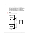
Connect the switch between pins J3.14 and J3.15 on the AUX Output and
Isolated Analog Programming Connector.
Defining the Interlock Mode
The Interlock mode is controlled via SCPI commands. There is no front
panel access for enabling or disabling the Interlock functionality. See
“Interlock Enable/Disable” on page 5–63.
The SCPI command for setting the Interlock mode to On and Off is:
[:]SENSe[<channel>]:PROTection:INTerlock[:STATe]
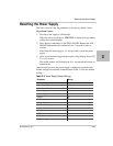
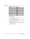
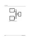
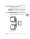
Power On Status Signal
Power On Status signal indicates a fault condition in the power supply.
Power On Status signal is a TTL output signal at Pin
J2.13 with reference
to COM_ISOLATED (Pin
J2.2 or Pin J2.6).
During normal operation, the Power On Status signal will be high. If the
output is disabled for any reason, the Power On Status signal will go low.
The following conditions will set the Power On Status to a low level:
•AC fail
• Over Voltage protection
• Over Temperature protection (OTP)
• Foldback protection
•Interlock
•Output Off


