Introduction
975-0200-01-01 4-3
4
Remote Programming Options
Analog Monitor Signals
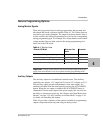
There are four monitor lines for analog programming the pin name and
the related APG mode, which are listed in
Table 4-1. All of these lines are
provided to give analog feedback. The output from these monitor lines is
a value scaled to the Analog Programming level set for the corresponding
analog programming type. For example, the voltage monitor and isolated
voltage monitor lines are both scaled to the analog programming level
that is set in the VAP mode.
Auxiliary Outputs
The auxiliary outputs are an additional isolated source. The auxiliary
output has two outputs: +5
V output on J3.9 and a +15 V output on J3.11.
The auxiliary output operates independently of the main output. It is
enabled or disabled from the front panel by pressing the AUX ON/OFF
button. When the Aux output is enabled, the AUX ON/OFF button is
illuminated. Like the main output of the power supply, the Aux also has
the ability to Autostart at power up. See
“Output Auto Start Mode (Auto
Restart)” on page 3–15 and “Auxiliary Auto Start Mode” on page 3–16
for details on controlling this feature.
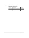
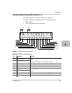
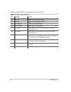
Table 4-2 provides a summary of the options available for programming
output voltage and current set point using an analog source.
Table 4-1
Monitor Lines
Related APG Mode Reference Line
Name
Connector
Non-Isolated Voltage Analog Programming VOL_MON J1.13
Isolated Voltage Analog Programming IS_MON_VOL J3.5
Non-Isolated Current Analog Programming CUR_MON J1.14
Isolated Current Analog Programming IS_MON_CUR J3.10
Important:
Analog control monitor lines will reflect the output of the power
supply even when the unit is not set to operate in analog programming mode.


