


SYSTEM CONNECTIONS
7-2 XEROX DOCUPRINT 4850/4890 IPS INSTALLATION PLANNING GUIDE
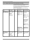
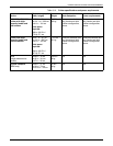
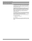
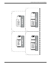
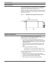
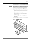
Cable locations
To run the cables beneath the flooring effectively, it is necessary to
know where the cables enter and exit the printer. The following
diagrams show those locations (marked with an X).
All power cords attach to the back of the printer. Listed below are the
distances of the printer power cord attachments from the left end of
the printer as you face it.
Figure 7-1. 4850/4890 cable enter/exit location (top view)
Channel attachments
The IPS printing system conforms to IBM standards and
requirements for any channel-attached printer. When you channel-
attach your printer, keep the following in mind:
• Channel length is usually determined by the length of the
cables, the number of devices on the channel, and the number
of connections in the cable itself (for example, connecting two
cables to each other).
• Subtract 15 feet from the total allowable cable length for any
device attached to the channel or for any connection of two
cables.
• IBM channel cable lengths are as follows:
— Gray: 200 feet / 61 m (with one device, 185 feet / 56 m)
— Blue: 400 feet / 122 m (with one device, 385 feet / 117 m)
For further information regarding IBM channel connections, refer to
the following IBM manuals:
• IBM System 360 and System 370 Input-output Interface
Channel to Control Unit OEM Information (#GA22-6974-3825)
• Page Printer Product Description (#G544-3482)
• 3825 Introduction and Planning Guide (#G544-3480).
4 in / 10 cm
4 in / 10 cm
1
23