


Zebra 105SL User’s Guide 105
®®lcàÍ_ÍÍÍÍlYÏÃÆ
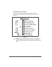
3ULQWHU,QWHUIDFH7HFKQLFDO,QIRUPDWLRQ
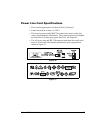
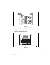
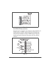
566HULDO'DWD3RUW
The connection for this standard interface is made through the female DB9
connector on the rear panel. A DB9 to DB25 interface module is required
for all RS-232 connections through a DB25 cable (see page 108 for
details).
For all RS-232 input and output signals, the printer follows both the
Electronics Industries Association’s (EIA) RS-232 specifications and the
Consultative Committee for International Telegraph and Telephone
(CCITT) V.24 standard signal level specifications.
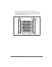
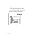
Table 4 shows the pin configuration and function of the rear panel serial
data connector on the printer.
NOTE: An interface module is required for RS-422/RS-485
interface support (see page 109).
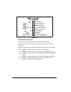
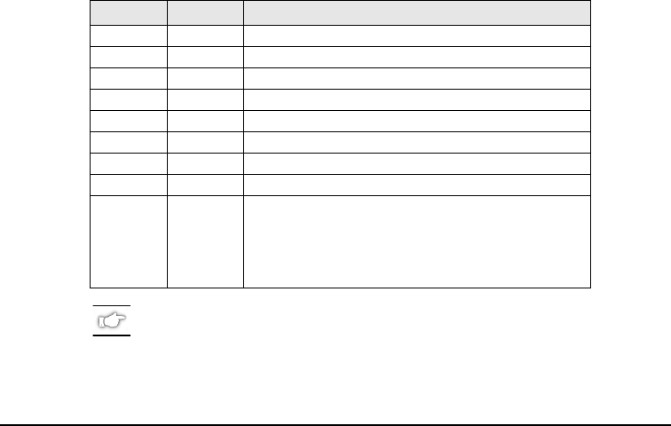
Table 4
Pin No. Name Description
1 — Not connected
2 RXD Receive data — data input to printer
3 TXD Transmit data — data output from printer
4 DTR Data terminal ready — output from printer
5 SG Signal ground
6 DSR Data set ready — input to printer
7 RTS Request to send — output from printer
8 CTS Clear to send — input to printer
9 +5VDC +5VDC signal output
NOTE: This pin is also available as a +5VDC power
source at 750mA. To enable this capability, a
jumper on the computer’s main logic board
needs to be installed on JP1, pins 2 and 3.