User's Guide
C-4 Interfaces
Power Line
The printer provides a +5 volts dc power line to drive the logic of an
external device.
Ground Lines
The printer provides fifteen ground lines consisting of a logic ground,
chassis ground, and thirteen signal return grounds.
Cable/Connector Requirements
The parallel connector must be a 36-pin male plug with a metal backshell
(Amphenol 157-32360 or equivalent). The cable must be shielded with
twisted pair leads (Beldon 9505 or equivalent). The parallel cable must
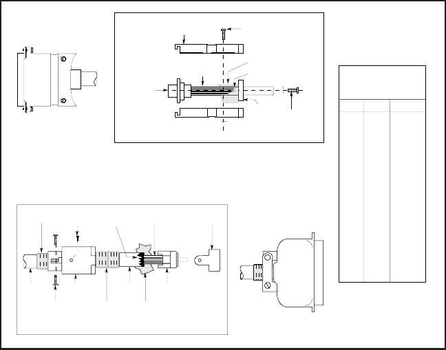
not exceed 10 feet (3 meters). Figure C-2 shows a typical parallel cable
assembly.
Figure C-2. Parallel Cable Assembly
AMT/IBM
PC WIRING
FROM TO SIGNAL
P1-1 P2-1 STROBE–
P1-2 P2-2 DB1
P1-3 P2-3 DB2
P1-4 P2-4 DB3
P1-5 P2-5 DB4
P1-6 P2-6 DB5
P1-7 P2-7 DB6
P1-8 P2-8 DB7
P1-9 P2-9 DB8
P1-10 P2-10 ACK–
P1-11 P2-11 BUSY
P1-12 P2-12 PAPER
P1-13 P2-13 SELIN–
P1-14 P2-14 AUTO FD–
P1-15 P2-32 ERROR–
P1-16 P2-31 IPRIME–
P1-17 P2-36 SELOUT
P1-18 P2-33 GND
P1-19 P2-19 GND
P1-20 P2-21 GND
P1-21 P2-23 GND
P1-22 P2-25 GND
P1-23 P2-27 GND
P1-24 P2-29 GND
P1-25 P2-30 GND
P2
CONNECTOR
SHROUD
CONNECTING
HARDWARE
(2 EA REQ'D)
HEAT-SHRINK
TUBING
CABLE
SHIELD
UNSHIELDED
WIRES
CABLE
CONNECTING
HARDWARE
(2 EA REQ'D)
BACKSHELL
HEAT-SHRINK
TUBING
CABLE CONNECTOR
COPPER
FOIL
RUBBER
BUSHING
MOUNTING
HARDWARE
(2 EA REQ'D)
CONNECTING
HARDWARE
(2 EA REQ'D)
UNSHIELDED
WIRES
DB-25
BACKSHELL
(2-PIECE)
COPPER FOIL
CABLE SHIELD
P1


