


B. Control Panel
1. Outline
The control panel contains a LCD (20 characters x 2 lines), 9 switches, and 7 LEDs.
The control panel is connected to the video controller PCB and has the functions listed below.
a. Displays status and error messages in the LCD.
b. Displays operation condition with the LED.
c. Changes Menus and values with the switches.
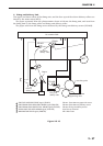
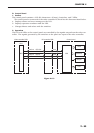
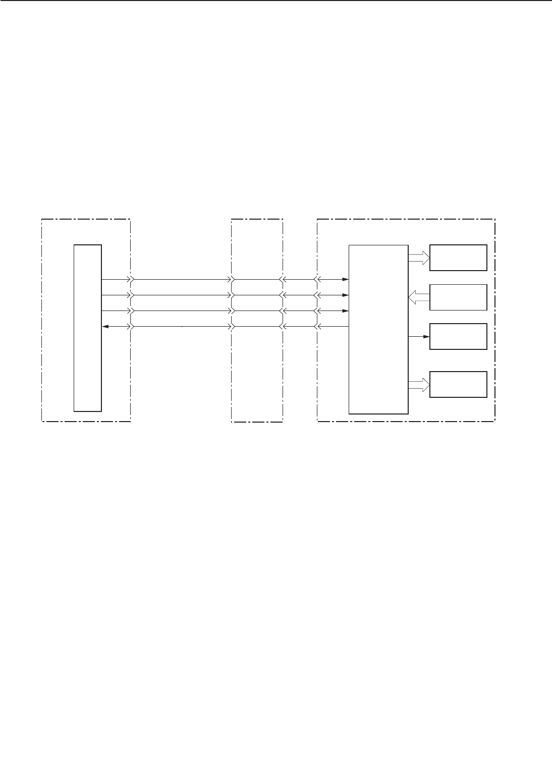
2. Operation
The LCD and LEDs on the control panel are controlled by the signals output from the video con-
troller. The signals generated by the switches on the panel are input to the video controller.
Figure 2-6-3
2 - 65
CHAPTER 2
nFP CLK
J6-C13
J3-3
nFP CS
J3-4
J3-5
J3-6
LEDs
LCD
CPU
Switches
IC10
Video controller PCB
AIR
nFP DI
nFP OD
J6-A14
J6-C14
J6-B14
DC controller PCB Control panel
Beeper