


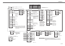


II. ENGINE CONTROL SYSTEM
A. DC Controller Circuit
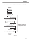
1. Outline
Operation sequences of the printer are controlled by the CPU of this circuit. When DC power is
supplied from the power supply by turning ON the power switch of the printer and the printer
enters the standby mode, the CPU outputs the signals that drive the loads such as laser diode,
motors, and solenoids, based on the print start command and image data.
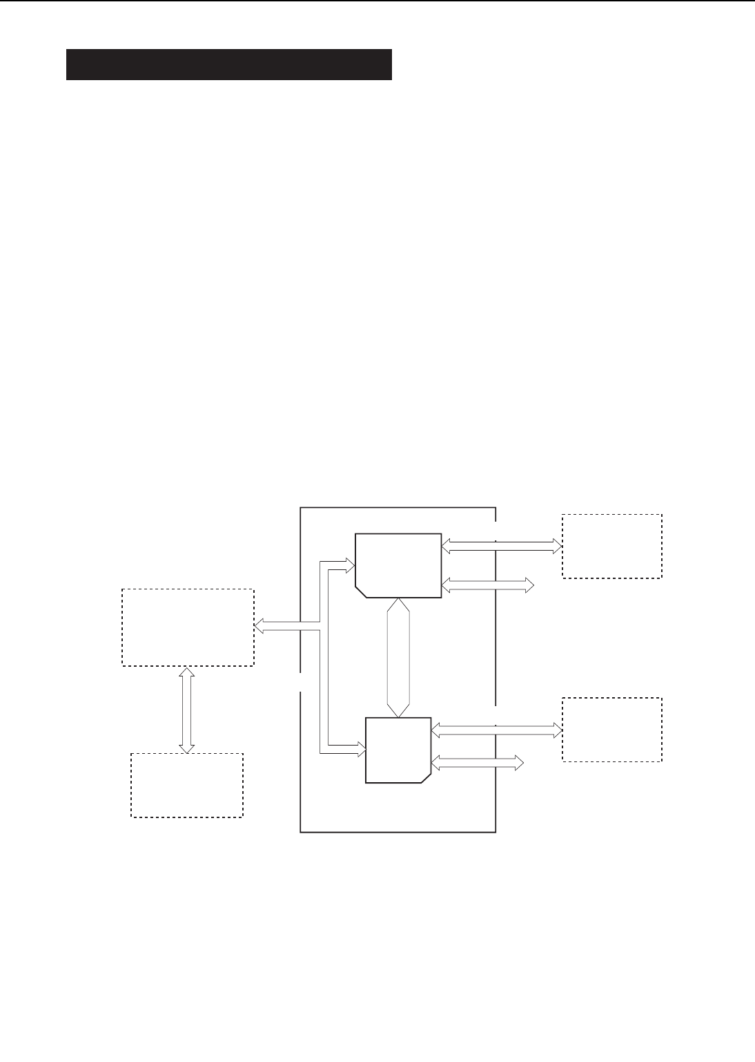
2. Explanation of operations of each block
a. CPU (IC201)
An 8-bit single chip microcomputer (UPD78056) by NEC is used.
The CPU is a one-chip type in which ROM and RAM are built in, and controls the operation of
the engine according to the control program stored in the ROM.
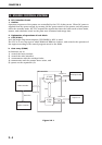
b. Gate array (IC202)
Its functions are to:
1) control the laser/scanner,
2) control the video interface,
3) communicate with the envelope feeder,
4) communicate with the printer driver tester, and
5) operate as the expansion I/O.
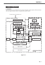
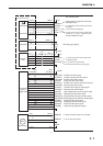
Figure 2-2-1
2 - 4
CHAPTER 2
Bus
Envelope feeder
Serial line
DC controller
Duplex unit
I/O
I/O
IC 201
CPU
IC 202
Gate array
Serial line
Serial line
Serial line
Video controller
Option controller