


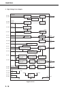
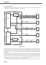

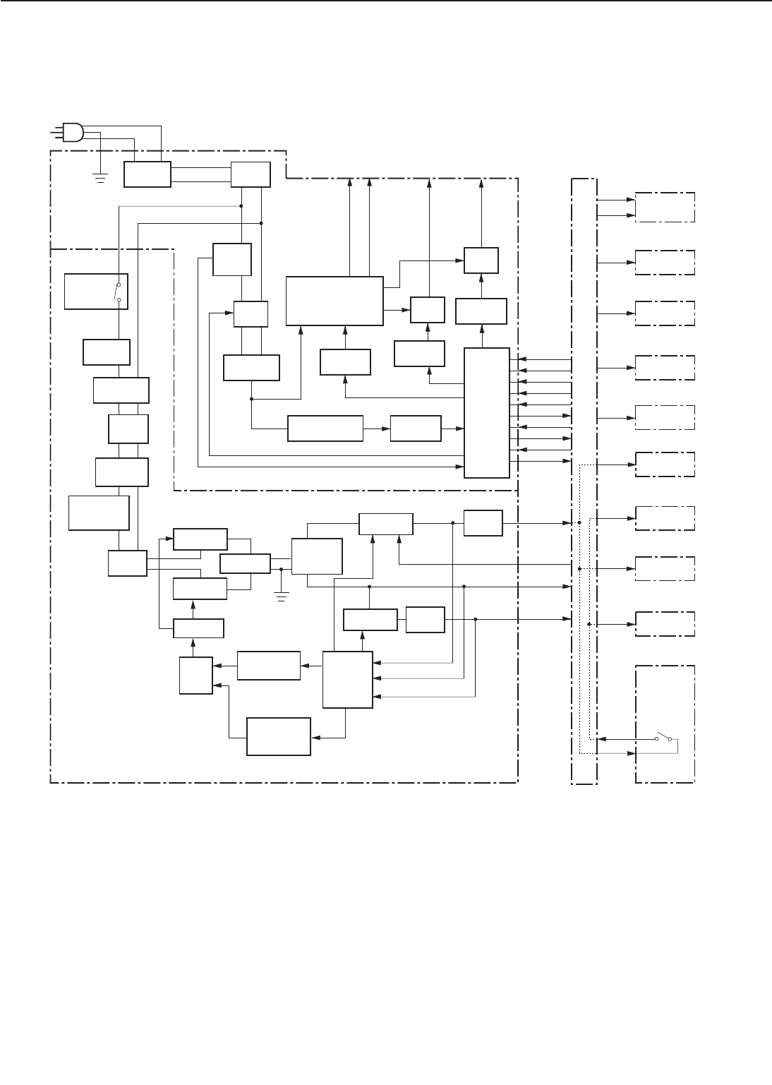
D. Power Supply
1. Outline
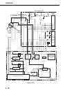
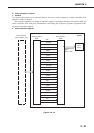
Figure 2-2-11
AC power is supplied to the low-voltage power supply when the main switch (S101) is turned
ON. The low-voltage power supply generates the required +24VDC, +5VDC and +3.3VDC for the
printer. +24VDC is supplied to the DC controller from the low-voltage power supply when the
DC controller sets the REMOTE 24V signal (/REMT24) to "L."
+24VDC is supplied to the high-voltage power supply PCB, +5VDC main motor, scanner motor,
and fans. +5VDC is used for sensors and ICs on the DC controller PCB.
+24VDC is divided into +24VA which is normally supplied from the power supply and +24VB
which is shut OFF when the door switch (SW1401) is turned OFF by opening the top cover or
2 - 19
CHAPTER 2
FSRTH
RLD
/FSRD1
/FSRD2
/FSRDE
/FSRCT
SUPSLT
/RLDSNS
TSWIN
TSWOUT
+5V
+24VA
+24VB
+5V
+24VA
+5V
+24VB
+24VA
+5V
+24VB
Over-current
detection circuit
Current
and
voltage
detection
circuit
+5V control
photocoupler
+3.3V
+5V
/REMT24
+24V
+3.3V
+5V
Converter
Current
transfor
-mer
Safety
circuit
Heater
drive
circuit
Triac
Current
fuse
Relay
Circuit
breaker
Noise
filter
Transformer
Power
switch
(S101)
Power supply
Low-voltage power supply circuit
Video
controller PCB
Scanner
motor
Main motor
Sensors
Switch
/sensor
PCB
Door
switch
(SW1401)
Laser driver
Solenoids
Clutches
Operation
panel
High-voltage
power supply
To fixing roller heater DC controller
BD PCB
Triac
Phototriac
coupler
Phototriac
coupler
Phototriac
coupler
Control
IC
Switching
FET
Switching
FET
Switching
FET
Switching
FET
Transformer
Noise
filter
Phototriac
coupler
Rectificat
ion circuit
Rectificat
ion circuit
Filter
circuit
Filter
circuit
Filter
circuit
Rectificat
ion filter
circuit
Rush curren
t
prevention
circuit
Abnormal
voltage latch
photocoupler
Inverter control
circuit