


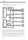

F. Other Controls
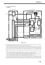
1. Main motor control
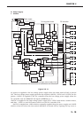
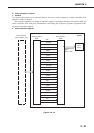
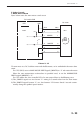
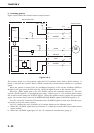
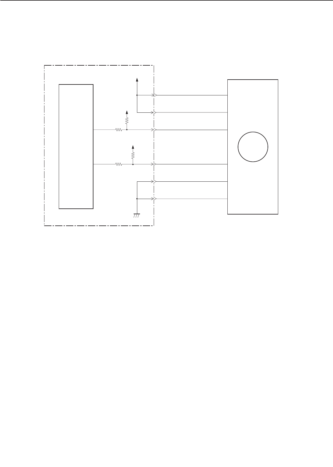
Figure below shows the main motor control circuit.
Figure 2-2-13
The main motor is a DC brushless motor with hall elements, and is unified with the motor drive
circuit.
The CPU (IC201) sets the MAIN MOTOR DRIVE signal (/MMOTD) to “L” and rotates the main
motor.
When the main motor rotates and reaches its specified speed, it sets the MAIN MOTOR
READY signal (/MMRDY) to “L.”
The CPU notifies the video controller PCB of a main motor failure in the following cases:
1) The /MMRDY signal does not become “L” withing 2.5 seconds after from the main motor
rotation starts.
2) The /MMRDY signal becomes “L” once, but becomes “H” for more than 0.1 seconds contin-
uously during the specified speed rotation.
2 - 23
CHAPTER 2
CPU
-2
39
-3
-4
M
-1
-6
J218-5
/MMOTD
MT1
/MMRDY
+5V
38
P62
+5V
IC201
-2
-3
-4
-1
-6
J36-5
P63
Main motor
DC controller PCB
+24VB