


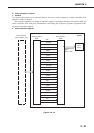

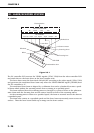
2. Fan motor control
This printer has 4 heat exhausting fans and an air intake fan. They are DC brushless motors.
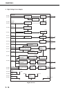
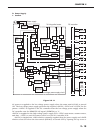
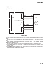
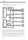
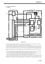
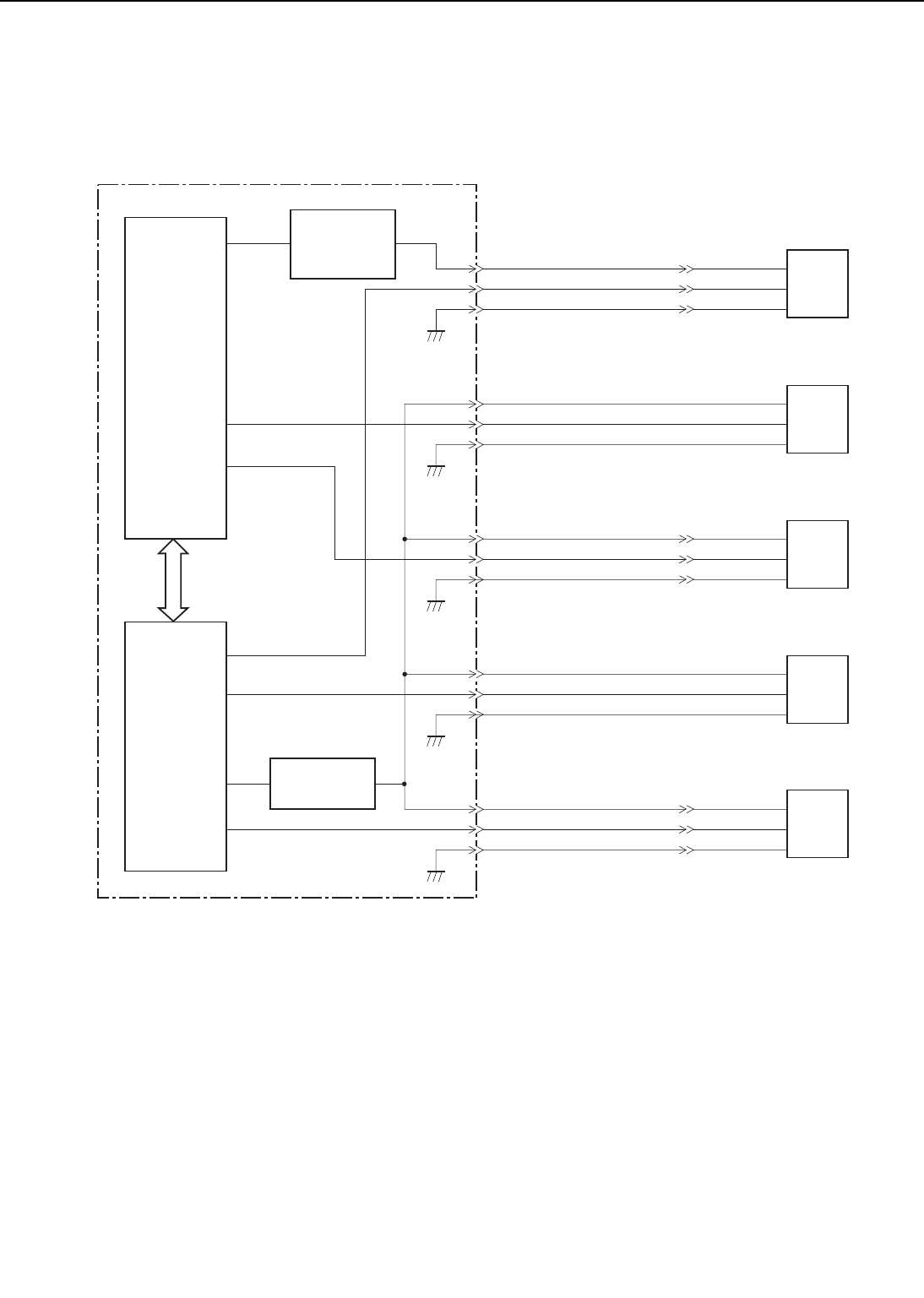
The figure below shows the fan motor control circuit.
Figure 2-2-14
When the power switch of the printer is turned ON, the CPU (IC201) on the DC controller sets
the No.53 pin to "H" and rotates the multi-purpose tray fan (FM5) at half speed for about 15 sec-
onds. The CPU sets the No.65 pin to "H" via the gate array (IC202), and rotates the power sup-
ply fan (FM1), fixing unit/scanner fan (FM2), electrical unit fan (FM3), and fixing unit fan (FM4)
at half speed.
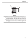
When it receives a /PRNT signal from the video controller, the CPU rotates FM1, FM2, FM3,
and FM4 at full speed and FM5 at half speed (full speed in case of duplex printing). When the
main motor drive stops after printing, the CPU rotates FM1, FM2, FM3, and FM4 at full speed
for about 30 seconds then at half speed. The CPU rotates FM5 at half speed for about 30 sec-
onds (full speed for about 30 seconds in case of duplex printing).
The drive voltages output from the fan motor drive circuit and multi-purpose tray fan motor
2 - 24
CHAPTER 2
FM5
J35-1
-2
-3
FAN5D
/FAN5S
GND
J34-3
-2
-1
J229-1
-2
-3
FM2
FAN2D
/FAN2S
GND
J216-1
-2
-3
FM3
J13-1
-2
-3
FAN3D
/FAN3S
GND
J12-3
-2
-1
J210-1
-2
-3
FM1
FAN1D
/FAN1S
GND
J208-1
-2
-3
FM4
J26-1
-2
-3
FAN4D
/FAN4S
GND
J25-3
-2
-1
J225-1
-2
-3
Multi-purpose
tray fan motor
drive circuit
Fan motor
drive circuit
65
DC14
IC202
(G.A.)
52
37
64
61
124
53
DA04
DA05
DA03
P121
P120
P61
IC201
(CUP)
DC controller PCB
Power supply
fan
Fixing unit/
Scanner unit
fan
Electrical unit
fan
Fixing unit fan
Multi-purpose
tray fan