


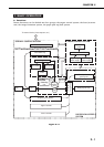
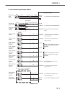
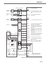
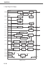
Figure 2-2-6
2 - 9
CHAPTER 2
+24VA
J1303-2
-1
CL3
J1302-2
-1
SL2
/MPTSLD
-5-5
/MTPCLD
-4-4
+24VA
J1402-2
-1
SL3
/FUSLD
J205-10J1401-13
H2
H1
S101
RLD
/FSRD1
/FSRD2
FSRDE
FSRCT
SUPSLT
/RLDSNS
PSTYP
/REMT24
J217-2
-6
-7
-8
-9
-10
-11
-12
-13
-1
-3
-5
-4
RY151
J54
J55
J10-1
-4
-3
-2
J50-6
J50-4
J50-3
J50-5
FSRN1
FSRL1
FSRL2
FSRN2
J214-2J1301-2
J222-2
-3
FSRTH
J50B-5
-4
TH
J56-2
-1
J51-2
-1
J222-1
-4
TSWOUT
TSWIN
J50B-6
-3
TSW
J52
J53
J102-2
-6
-7
-8
-9
-10
-11
-12
-13
-1
-3
-5
-4
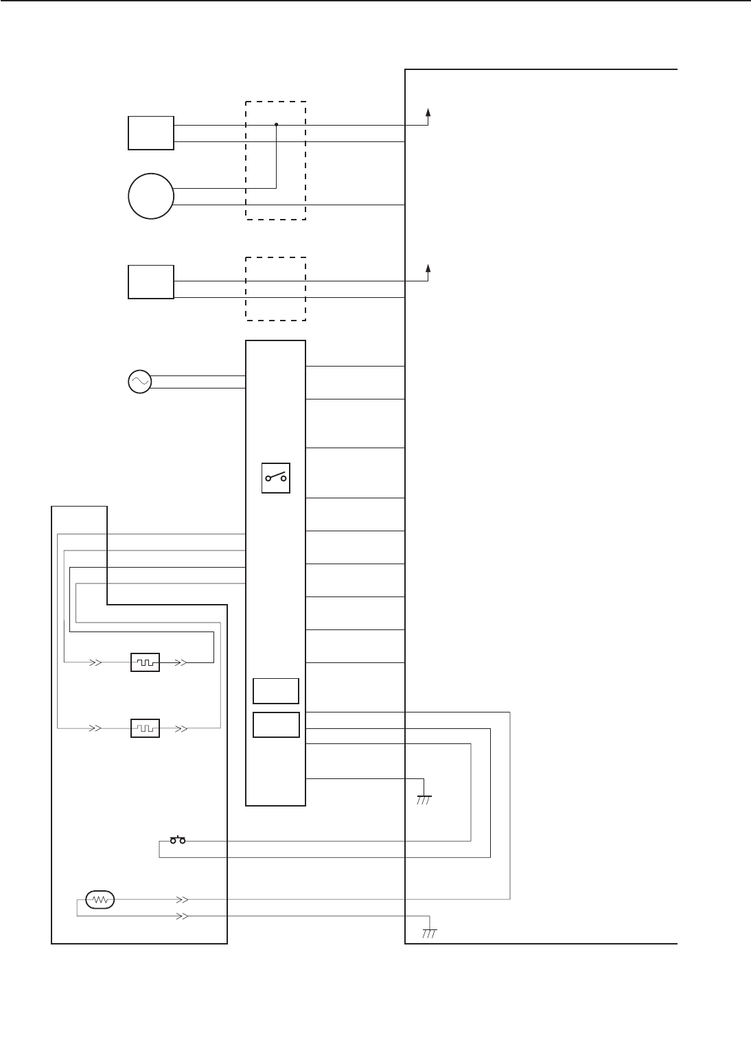
DC controller PCB
Manual feed
clutch
Lifting plate
solenoid
Multi-purpose tray PCB
"L" to rotate the manual feeding
pick-up roller.
"L" to drive the lifting plate. If the
plate is up it will drop, if down it will
rise.
Face-up
solenoid
Switch/sensor PCB
"L" to deliver printed paper face up.
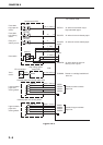
Fixing main heater
Fixing sub heater
Thermo-switch
Fixing unit
Power
supply
Power
switch
Relay
AC power
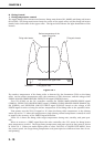
The voltage drops as the
fixing roller temperature
rises.
Fixing roller
surface
temperature
sensor
RY152
"L" to turn OFF the relay and interrupt
the power to the fixing heater.
The main heater is turned ON when
the FSRDE signal is output and this
signal is "L."
The sub heater is turned ON when
the FSRDE signal is output and this
signal is "L."
Fixing heater drive enable signal
(pulse signal)
"L" when the current transformer
detects the power to the fixing heater.
Inverter circuit control signal.
"L" when the relay is turned ON.
"L" when the line voltage is 200V (for
200V model only)
When "L", the power supply uni
t
outputs 24V to the DC controller.