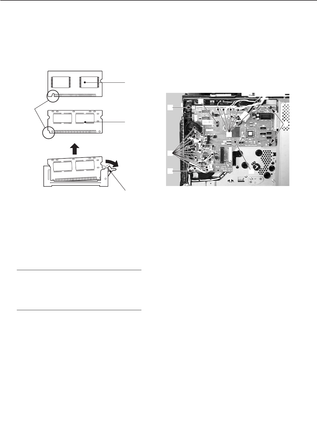
b. Removal of RAM DIMM/ROM DIMM
(option)
1) Push down the socket lever to remove
the RAM DIMM or ROM DIMM. Be sure
not to touch the elements.
➀ Socket lever
➁ RAM DIMM
➂ ROM DIMM
➃ Cutout
Figure 3-8-5
Note: When installing the RAM DIMM or
ROM DIMM onto the video con-
troller PCB, note that the shape of
the RAM DIMM cutout differs from
that of the ROM DIMM cutout.
C. DC Controller PCB
1) Remove the high-voltage power supply
unit following steps 1-3 on Page 3-47.
2) Disconnect the 19 connectors from the
DC controller PCB.
3) Remove the 2 screws (M3) and the 2
screws (M4).
4) Unhook the claw, and then remove the
DC controller PCB.
➀ Connectors
➁ Screws (M3)
➂ Screws (M4)
➃ Claw
➄ DC controller PCB
Figure 3-8-6
3 - 43
CHAPTER 3
➁
➁
➂
➀
➃
➄
➀
➀
➁
➂
➃


