


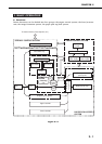
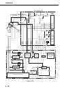
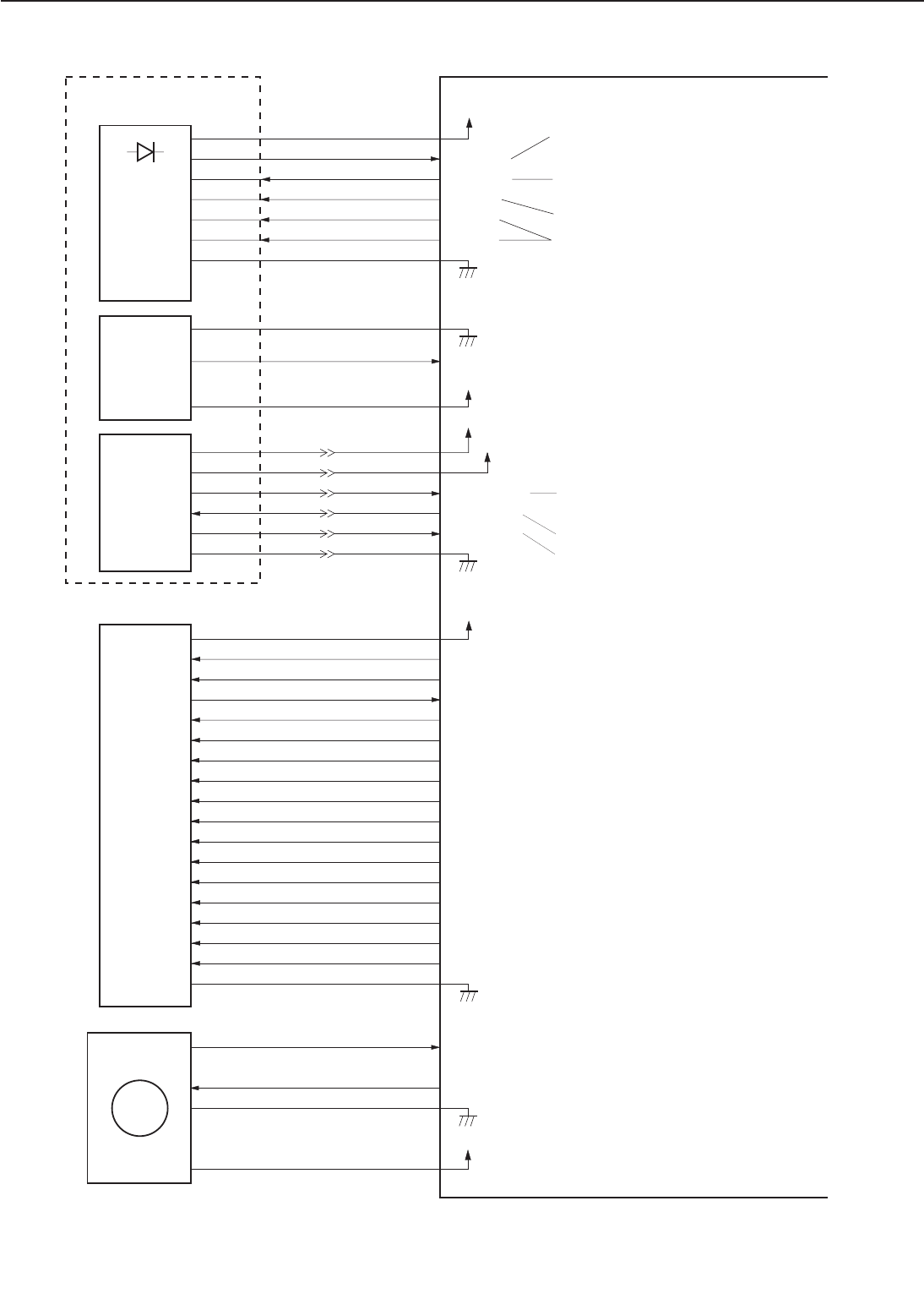
Figure 2-2-4
2 - 7
CHAPTER 2
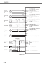
TRFVCNT
/TRFNVD
TRFVSNS
/HRLBD
/TRFCCD
/DCHGBD
/TRFCLK
/DCHGUP
HVTCLK
/DEVACD
PRIACCLK
DEVACCLK
/PRIACD
/DEVDCD
/PRIDCD
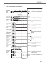
DENADJ
Transfer bias drive signal
Transfer negative bias drive signal
Transfer bias monitor signal
Fixing roller bias drive signal
Transfer bias constant current drive signal
Discharge bias drive signal
Transfer bias frequency output signal
Discharge bias switch signal
High voltage bias frequency output signal
Developing AC bias drive signal
Primary AC bias frequency output signal
Developing AC bias frequency output signal
Primary AC bias drive signal
Developing DC bias drive signal
Primary DC bias drive signal
Image density adjustment signal
Analog signal in proportion to the laser
intensity is input.
J202-4
-2
-11
-10
-7
-9
-3/-5/-8
J1001-8
-10
-1
-2
-5
-3
-4/-7/-9
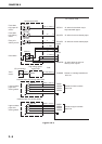
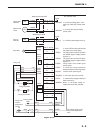
+5V
+24VB
DRVES
/LENBL
/LON
VDO
/VDO
J220
-A12/-B12
-A1
-B1
-A2
-B2
-A3
-B3
-A4
-B4
-A6
-A7
-B7
-A8
-B8
-A9
-B9
-B10
-A11/-B11
+5V
J206-1/-2J6-3/-4
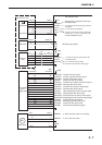
/BDI
-4
-3
-1
-2
/SCNRDY
/SCND
SCNCLK
J207-7
-1
-2
-3
-5
-4/-6
J1-1
-7
-6
-5
-3
-2/-4
+24VA
-1
-7
-6
-5
-3
-2/-4
+5V
-1
-7
-6
-5
-3
-2/-4
J18
J701
-A12/-B12
-A1
-B1
-A2
-B2
-A3
-B3
-A4
-B4
-A6
-A7
-B7
-A8
-B8
-A9
-B9
-B10
-A11/-B11
J218-1
-2
-3/-4
-5/-6
/MMRDY
/MMOTD
J12-1
-2
-3/-4
-5/-6
+24VB
MT1
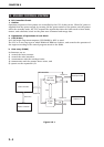
DC controller PCB
Laser diode
Laser driver
Laser/scanner unit
High-voltage
power
supply PCB
"L" when the scanner motor reaches the
prescribed speed.
"L" to drive the scanner motor.
Scanner motor reference clock signal.
Scanner
motor
BD PCB
BD input signal (pulse)
"L" when the main motor runs normally.
"L" to run the main motor.
Main motor
"L" to switch the laser ON according to the VDO and
/VDO signals.
"L" to turn thelaser ON compulsively.
The laser is turned ON only when the /LENBL, VDO,
and /VDO are "L", "H", and "L" respectively. (LOW-
VOLTAGE DIFFERENTIALsignal)