


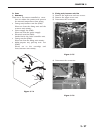
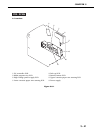
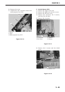
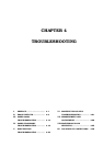

6) Remove the screw
7) Unhook the claw, and then remove the
multi-purpose tray PCB.
➀ Screw
➁ Claw
➂ Multi-purpose tray PCB
Figure 3-8-10
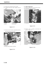
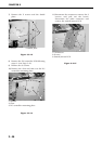
F. Switch/Sensor PCB
1) Remove the upper cover unit.
2) Remove the right rear and rear covers.
3) Remove the left rear cover.
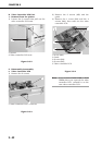
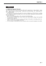
4) Remove the connector, the 2 screws,
and then the fan duct.
5) Remove the 4 screws.
➀ Connector ➁ Screws
➂ Fan duct ➃ Screws
Figure 3-8-11
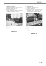
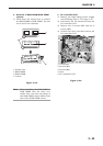
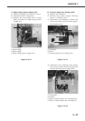
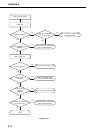
6) Remove the 3 screws and the shield
cover.
➀ Screws ➁ Shield cover
Figure 3-8-12
3 - 45
CHAPTER 3
➂
➀
➁
➃
➁
➀
➂
➀
➁