


3-17
Cisco MGX 8850 Multiservice Switch Installation and Configuration
Release 1.1.31, Part Number 78-11223-03 Rev. B0, May 2005
Chapter 3 Site Preparation
Power and Grounding
Note If the power requirement of installed cards exceeds the power capability of the system, an error
message is generated.
Caution Consult Cisco TAC if the plans for the MGX 8850 AC power include a portable, uninterruptible
power source (UPS). Cisco recommends a UPS with a low output impedance and the capacity to
provide the necessary fault current to trip the protection devices. Do not use a UPS or any power
source with a Ferro-Resonant transformer.
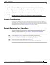
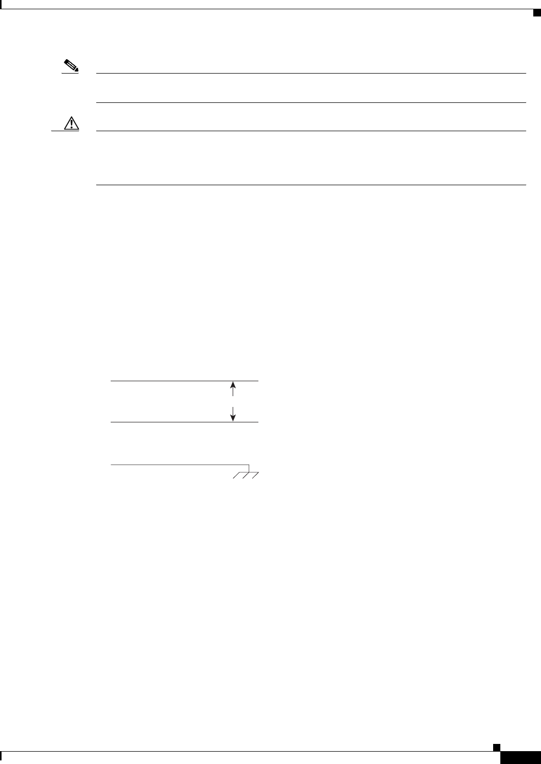
The power receptacles to which the node connects must be of the grounding type. The grounding
conductors that connect to the receptacles should connect to protective earth at the service equipment.
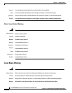
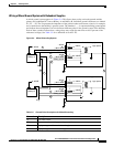
For reference, Figure 3-3 shows the electrical relationship in the three-wire wall plug.
Cisco can provide 220 VAC power cords with the following plugs:
• 20 A NEMA L620, 3-prong plug (U.S.)
• 13 A 250 VAC BS1363, 3-prong fused plug (UK, Ireland)
• CEE 7/7 (Continental Europe)
• AS3112 (Australia, New Zealand)
• CEI23-16/VII (Italy)
Figure 3-3 Electrical Relationship of AC Plug Wiring
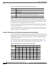
Electrical Power for DC-Powered Switches
This section describes the safety and standards-body compliance issues for DC-powered systems. For
the bonding and grounding issues related to electrical noise, see the Bonding and Grounding section that
follows.
The DC-powered model of the MGX 8850 uses one or two Power Entry Modules (PEMs) to accept DC
current. The DC PEMs should connect to a source capable of supplying 60 Amps of current. Each branch
circuit at the source should have a 60A circuit breaker, and the wires connecting the PEMs to the sources
should be capable of carrying 60A. A 6 AWG (10 square millimeters) copper wire is adequate. Also,
consult the local or national codes for conductor sizing for DC supply connections if necessary.
Conductors must be suitable for 60A.
Be sure to connect the grounding wire conduit to a solid earth ground. Cisco recommends a closed loop
to terminate the ground conductor at the ground stud.
In summary, note the following caution for DC systems:
H8397
L2
L1
200 to 240 VAC