


3-19
Cisco MGX 8850 Multiservice Switch Installation and Configuration
Release 1.1.31, Part Number 78-11223-03 Rev. B0, May 2005
Chapter 3 Site Preparation
Power and Grounding
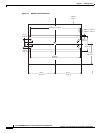
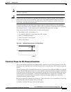
Wiring a Mixed Ground System with Redundant Supplies
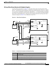
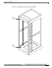
A mixed ground system appears in Figure 3-4. This figure shows safety and earth grounds and the
primary and redundant DC sources Battery A and Battery B. Individual ground conductors are labeled
Z1, Z2, ..., Z5. The Z represents the impedance of the ground conductor between a chassis, for example,
and a connection to the building’s ground system. The numbers 1, ..., 4 represent building ground points
and indicate that an impedance can exist between different points in the ground system of the building.
Each of these symbols indicate that a voltage drop may result (but must not exceed 2 percent of the
referenced voltage). See Table 3-2 for a definition of each Z1–Z5.
Figure 3-4 Mixed Grounding System
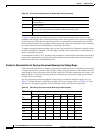
Table 3-2 Ground Point Descriptions for Mixed Grounding
Connection Description
Z1 –48 VDC return.
Z2 Protective earth or safety ground (green/yellow).
Z3 Equipment ground for non isolated equipment.
Z4 Equipment ground for isolated equipment.
Battery A
Nonisolated equipment
– 48V-A
T
– 48V-A
– 48V-A
logic power
+–
– 48V-B
1
1
B
2
B
T
T
Safety ground
Safety ground
Safety ground
– 48V-A RTN
– 48V-A
– 48V-A RTN
– 48V-B
– 48V-B RTN
– 48V-B
– 48V-B RTN
Safety ground
Battery B
– 48V-B
+–
Isolated equipment
– 48V-A logic power
– 48V-B
2
4
T
Z1
Z1
Z1
Z1
Z2
Z2
Z2
Z2
Z3
3
Z4
Z5
28311