


6-9
Cisco MGX 8850 Multiservice Switch Installation and Configuration
Release 1.1.31, Part Number 78-11223-03 Rev. B0, May 2005
Chapter 6 Card and Service Configuration
Processor Switching Module
For a feeder, you can activate only one line. For a stand-alone, you can activate more than one line if the
back card has multiple lines. One line must serve as the trunk to the ATM network. With an OC-3, T3,
or E3 card, remaining lines can serve as UNI ports to CPE.
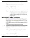
Step 3 If necessary, modify the characteristics of a line by entering the cnfln command.
Step 4 Configure logical ports for the physical line by entering the addport command. Enter the addport
command once for each logical port. Related commands are cnfport, dspports, and delport.
addport <port_num> <line_num> <pct_bw> <min_vpi> <max_vpi>
The following example uses 100% of the bandwidth on one logical port 1
addport 1 1 100 1 200
• The first “1” is the logical port number.
• The second “1” is the line number on the PXM1 back card to which you are assigning this logical
port number.
• “100” is the percentage of bandwidth this port has in both directions;
• The VPI range is 1–200.
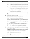
Step 5 If necessary, enter the cnfportrscprtn command to modify port-level resources for a controller
cnfportrscprtn <port_no> <controller> <ingress_%BW> <egress_%BW> <min_VPI> <max_VPI>
<min_VCI> <max_VCI> <max_GLCNs>
-ds3 Indicates a T3 line parameter follows.
-e3 Indicates an E3 line parameter follows.
-sonet Indicates an OC-3 or OC-12 line parameter follows.
slot Slot is 7 or 8 for the PXM1. If the shelf has a redundant pair of SRMs, enter
the addln command for slots 15, 16, 31, and 32
line The range is 1–4 but it depends on the number of lines on the back card.
port_num The number for the logical port. The range is 1–32 for user-ports or 34 for inband
ATM PVCs that serve as management connections
line_num The line number in the range 1–4 but depends on the type of uplink card
pct_bw The percentage of bandwidth. The range is 0–100. This parameter applies to both
ingress and egress
min_vpi The minimum VPI value. On a feeder, the range is 0–4095. On a stand-alone node,
the range is 0–255
max_vpi The maximum VPI value. On a feeder, the range is 0–4095. On a stand-alone node,
the range is 0–255