


4-8
Cisco MGX 8850 Multiservice Switch Installation and Configuration
Release 1.1.31, Part Number 78-11223-03 Rev. B0, May 2005
Chapter 4 Enclosure and Card Installation
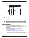
Open Rack Installations
Install the MGX 8850 without a Mechanical Lift (Optional)
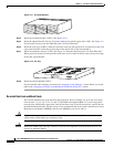
Because the MGX 8850 chassis with installed modules is too heavy to lift, a mechanical lift should be
used to install the switch into the rack.
If a mechanical lift is not available, the cards and power supplies should be removed before the chassis
is installed.
This section contains instructions to remove the cards, install the chassis into the rack, and re-install the
cards.
Warning
Removing and re-installing the cards and power supplies increases the chance of broken or bent
pins on the backplane. Be careful to properly align and install the cards and power supplies. To
avoid the possibility of bent or broken pins, and to simplify installation, Cisco Systems
recommends the use of a mechanical lift for open rack installations.
To install an MGX 8850 without a mechanical lift, see the following sections.
• Remove Front Cards, page 4-8.
• Remove Back Cards, page 4-9.
• Remove 220 VAC Power Supplies, page 4-9.
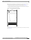
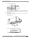
• Install the Enclosure, page 4-10.
Additional information is listed in Module Stacking Order, page 4-2.
• Re-install the Front and Back Cards, page 4-12
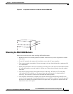
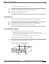
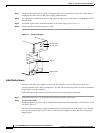
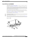
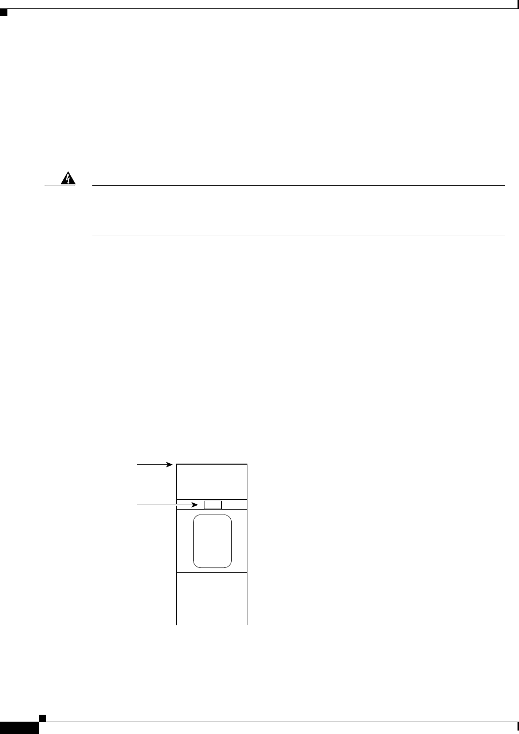
Remove Front Cards
A latch on each single-height front card secures it to the backplane.
Double-height cards have latches at the top and the bottom (see Figure 4-5).
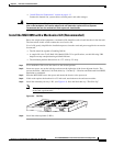
Figure 4-5 Front Card Insertion/Extractor Latch
Top of card
Slot
H8293