


4-17
Cisco MGX 8850 Multiservice Switch Installation and Configuration
Release 1.1.31, Part Number 78-11223-03 Rev. B0, May 2005
Chapter 4 Enclosure and Card Installation
Install Electrical Connections
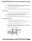
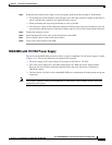
Step 4 Grasp the cable bracket at the captive screws and gently push the bracket straight in. Furthermore:
• To align the pins of the backplane and cable pins, move the cable connector slightly up and down or
side to side until the connectors are aligned and able to mate.
• When performing this step, keep the bracket as level as possible.
• The connector is fully inserted when the connector shell (housing) easily moves all the way in to the
enclosure hole and the exterior of the shell with the captive screws is fully flush with the enclosure.
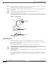
Step 5 Tighten the connector screws.
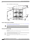
Step 6 Attach the three DC source wires at the wiring block on the PEM.
Step 7 Turn on the DC power at the circuit branch source.
Step 8 Turn on the circuit breaker of the PEM.
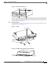
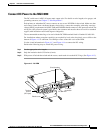
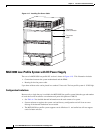
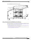
MGX 8850 with 110 VAC Power Supply
The version of the MGX 8850 powered by either a single or redundant 110 VAC power supply is shown
in Figure 4-15. The version shown has the optional door installed.
• The power supply will accept voltages in the ranges of 100 VAC to 130 VAC.
• The 110V power supply has a maximum output power of 1200W per power supply module.
However, because of safety limitations imposed on the line cord, the power is restricted to
1000 Watts output.
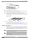
• The Low Profile 110 VAC version of the MGX 8850 has a combination air intake plenum and power
supply tray.
Note The system is limited to using cards from Release 1.1 and earlier. Cards in future releases will not be
supported by this system.