


4-22
Cisco MGX 8850 Multiservice Switch Installation and Configuration
Release 1.1.31, Part Number 78-11223-03 Rev. B0, May 2005
Chapter 4 Enclosure and Card Installation
Install the Cable Manager
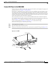
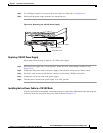
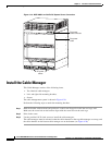
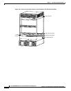
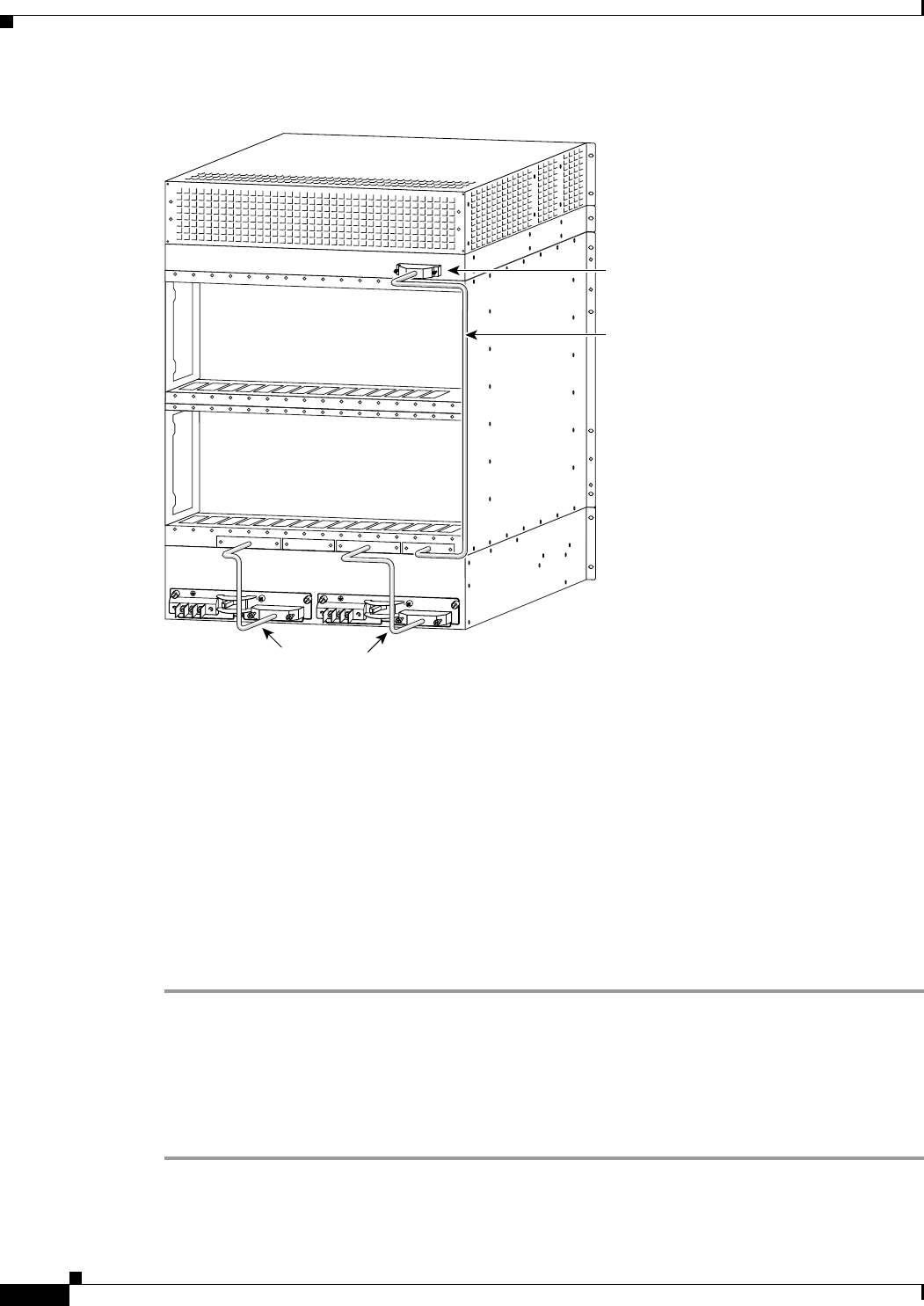
Figure 4-19 MGX 8850 Low-Profile DC System Power Connection.
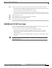
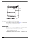
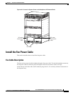
Install the Cable Manager
This Cable Manager consists of the following items.
• Two identical cable managers.
• Left- and right-side mounting brackets.
• Screws.
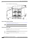
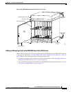
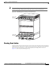
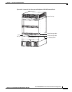
The cable management system is shown in Figure 4-20.
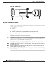
Perform the following steps to attach the mounting brackets:
Step 1 Hold the bracket with one hand and position it so the lower flange fits inside the card cage wall.
Make sure the screw hole on the bracket aligns with the screw hole on the card cage.
Step 2 Drive in the screw.
Step 3 Use the provided 10-32 sized screws to install the cable managers.
The cable managers must be oriented so that the cable channels on the top cable manager are on top, and
the cable channels on the bottom cable manager are on the bottom (see Figure 4-20).
30367
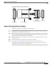
Fan power
cable connecto
r
Fan power
cable
-48V
OFF
ON
RTN
DC OK
J1
-48V
OFF
ON
RTN
DC OK
J1
DC power
cables