


2-18
Cisco MGX 8850 Multiservice Switch Installation and Configuration
Release 1.1.31, Part Number 78-11223-03 Rev. B0, May 2005
Chapter 2 Module and Service Descriptions
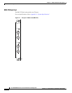
ATM UNI Service Module (AUSM)
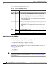
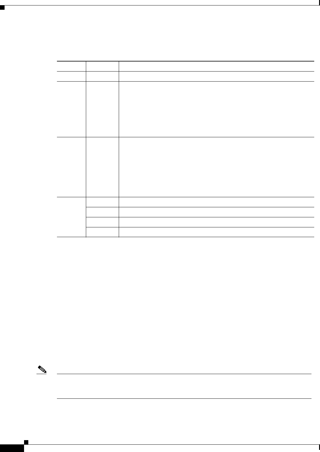
Table 2-3 contains a list of eight-port LED indicators:
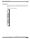
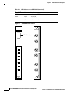
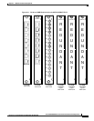
Back Cards for the AUSM/B
The MGX-AUSM-8T1/B and MGX-AUSM-8E1/B use the generic eight-port T1 or E1 line modules that
operate with the eight-port service modules (see Figure 2-11).
• AX-RJ48-T1: provides eight RJ-48 connectors for T1 lines.
• AX-RJ48-E1: provides eight RJ-48 connectors for E1 lines.
• AX-SMB-E1: provides eight pairs of SMB connectors for E1 lines.
1:N Redundancy support for the AUSM requires the special versions of the RJ-45 back cards (see
Figure 2-11). These back cards are
• AX-R-RJ48-T1
• AX-R-RJ48-E1
• AX-R-SMB-E1
Note Redundancy support differs for the MGX-AUSM-8T1/B and MGX-AUSM-8E1/B. For details on the
requirements for redundancy through an MGX-SRM-3T3/C, see the ““Service Resource Module”
section on page 2-12.”
Table 2-3 Eight-Port AUSM-B LED Indicators
LED Color Description
ACT Green On indicates the card set is in active mode.
STBY Yellow
• Slow blink with Active LED off means the card is in the boot state.
• Fast blink with Standby LED on means card is receiving firmware.
• Fast blink indicates the service module is passing BRAM channel
information to the PXM1.
• Steady yellow indicates the card is in Standby mode and the firmware
is executing ADMIN code.
FAIL Red
• Steady Red with Active and Standby LEDs off indicates either the card
is in the Reset condition, the card has failed, or the card set is not
complete (no line module).
• Steady Red with Active LED on indicates the card was active prior to
failing.
• Steady Red with Standby LED on indicates the card was standby prior
to failing.
PORT Green Green indicates the port is active.
Red Red indicates a local alarm on the port.
Yellow Yellow indicates a remote alarm on the port.
Off indicates the port has not been activated (upped).