


A-32
Cisco MGX 8850 Multiservice Switch Installation and Configuration
Release 1.1.31, Part Number 78-11223-03 Rev. B0, May 2005
Appendix A System Specifications
Circuit Emulation Service Module for T1 Operation
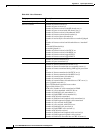
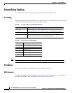
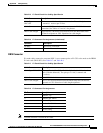
• Number of end-end loop-back cells received
• Number of segment loop-back cells received
• Number of OAM cells discarded due to CRC-10 error
The diagnostics report the header of last cell with an unknown logical connection number LCN.
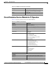
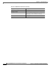
Circuit Emulation Service Module for T1 Operation
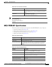
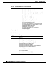
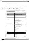
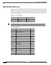
Table A-34 describes operational details for the MGX-CESM-8T1 and MGX-CESM-8E1.
Table A-34 CESM 8T1 Card Information
Category Description
Back Card RJ48-8T1
Line Rate T1: 1.544 Mbps ±75 bps (50 ppm)
Transmit Clocking Normal clock or SRTS generated
Line Coding B8ZS
AMI
Frame mode SF
ESF
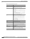
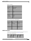
Line alarms Loss of signal (LOS)
Loss of frame (LOF)
Loss of multiframe (LOMF)
Remote loss of signal or frame (RAI)
All ones received (AIS)
Bipolar violation
Alarm indication times Near end alarm up-count
Near end alarm down-count
Near end alarm maximum count
Far end alarm up-count
Far end alarm down-count
Far end alarm maximum count
Supported OAM cells AIS
FERF
End-to-end loopback
Segment loopback
RTD loopback
BCM
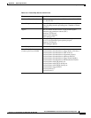
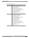
Physical Layer Performance
Statistics
—
LED Indicators Per Card Active (green), Failed (red), Standby (yellow)
BERT T1 E1 1.2
1-to-N Redundancy Active (green)
Indicator for each T1 Active (green)
Reliability, MTBF —