


2-23
Cisco MGX 8850 Multiservice Switch Installation and Configuration
Release 1.1.31, Part Number 78-11223-03 Rev. B0, May 2005
Chapter 2 Module and Service Descriptions
Frame Relay Service Modules
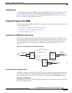
1:N Redundancy
1:N redundancy for the eight-port FRSMs requires an MGX-SRM-3T3/C. With 1:N redundancy, a group
of service modules includes one standby module. For installation requirements, see the “Service
Resource Module” section on page 2-12”. For configuration requirements, see Chapter 6, “Card and
Service Configuration” MGX-SRM-3T3/C section.
Connection Types on the FRSM
The following sections describe NIW, SIW, FUNI, and Frame forwarding. Topics include translation and
congestion management.
• Frame Relay-to-ATM Service Interworking, page 2-24
• ATM Frame-to-User Network Interface, page 2-27
• Frame Forwarding, page 2-26
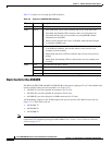
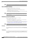
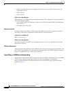
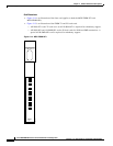
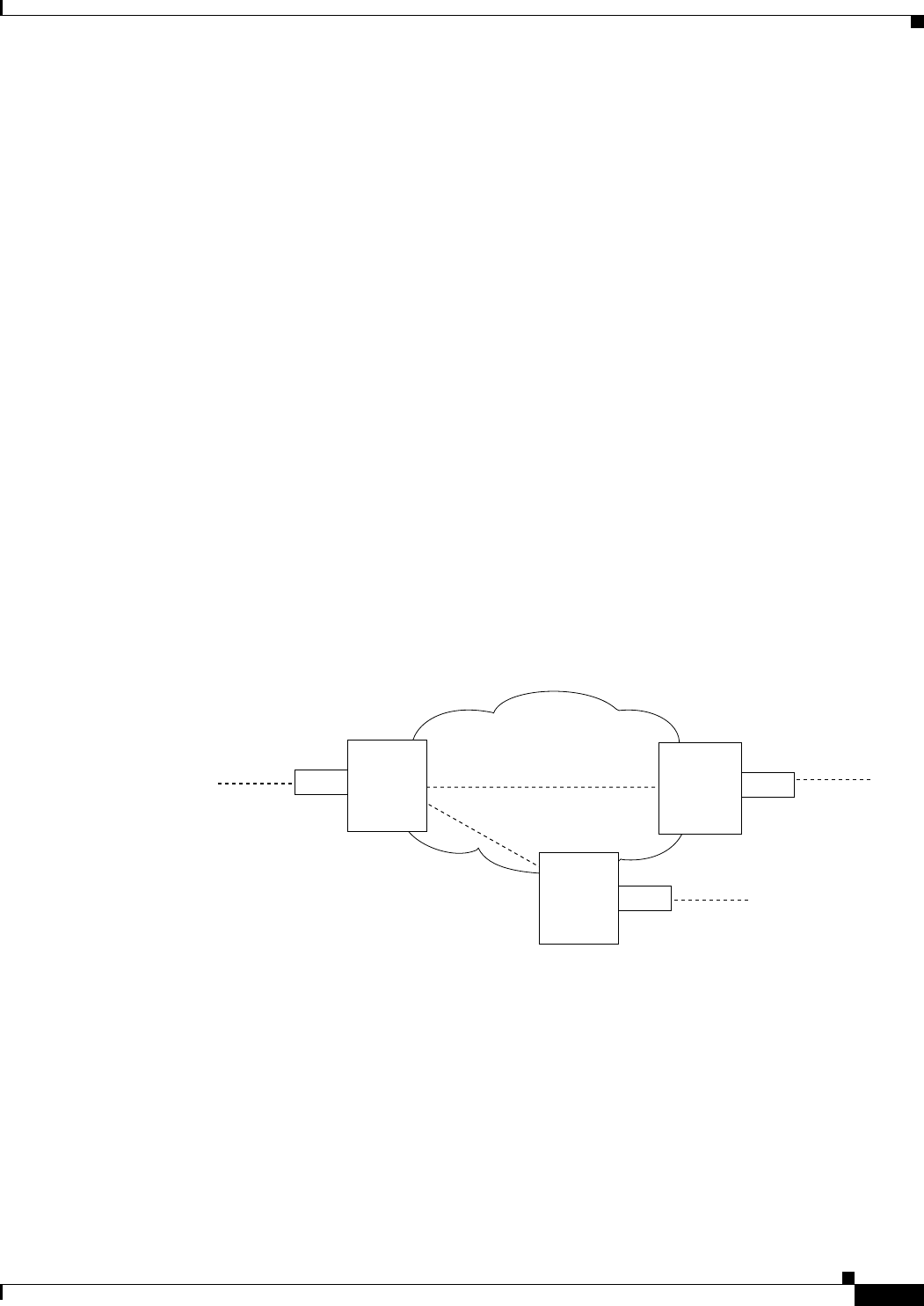
Frame Relay-to-ATM Network Interworking
Frame Relay-to-ATM network interworking (NIW) supports a permanent virtual connection (PVC)
between two Frame Relay users over a Cisco network or a multi-vendor network. The traffic crosses the
network as ATM cells. To specify NIW for a connection, add the connection with a channel type of
“network interworking.” For an illustration of a BPX 8620 network with NIW connections, see
Figure 2-12.
Figure 2-12 BPX 8620 Network with NIW Connections
Congestion Indication for NIW Connections
In addition to frame-to-cell and DLCI to VPI/VCI conversion, the network interworking feature maps
cell loss priority (CLP) and congestion information from Frame Relay to ATM formats. The CLP and
congestion indicators can be modified for individual connections using the cnfchanmap command.
Frame Relay–to–ATM Direction
Each Frame Relay-to-ATM network interworking connection can be configured as one of the following
DE to CLP mapping schemes:
MGX 8850
MGX 8850
FRSM
FRSM
Frame Relay
DS1
Frame Relay
DS1
FRAD
(router)
Frame Relay
DS1
FRAD
(router)
FRAD
(router)
BPX 8620 network
PVCs
FRSM
MGX 8850
17908