


2-24
Cisco MGX 8850 Multiservice Switch Installation and Configuration
Release 1.1.31, Part Number 78-11223-03 Rev. B0, May 2005
Chapter 2 Module and Service Descriptions
Frame Relay Service Modules
• DE bit in the Frame Relay frame is mapped to the CLP bit of every ATM cell generated by the
segmentation process.
• CLP is always 0.
• CLP is always 1.
ATM–to–Frame Relay Direction
Each Frame Relay to ATM network interworking connection can be configured as one of the following
CLP to DE mapping schemes:
• If one or more ATM cells belonging to a frame has its CLP field set, the DE field of the Frame Relay
frame will be set.
• No mapping from CLP to DE.
Congestion Indication
Congestion on the Frame Relay to ATM network interworking connection is flagged by the EFCI bit.
The setting of this feature is dependent on traffic direction, as described below.
Frame Relay–to–ATM Direction
EFCI is always set to 0.
ATM–to–Frame Relay Direction
If the EFCI field in the last ATM cell of a segmented frame received is set, then FECN of the Frame
Relay frame will be set.
PVC Status Management
The management of the ATM layer and the FR PVC status management can operate independently. The
PVC status from the ATM layer is used when determining the status of the FR PVC. However, no direct
actions of mapping LMI A bit to OAM AIS is performed.
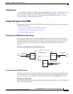
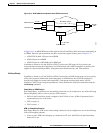
Frame Relay-to-ATM Service Interworking
By specifying “service interworking” as the channel type when adding a Frame Relay PVC to an FRSM,
all PVC data is subject to service interworking translation and mapping in both the Frame
Relay–to–ATM and ATM–to–Frame Relay directions. An illustration of typical SIW connections is
shown in Figure 2-13.