


4-10
Cisco MGX 8850 Multiservice Switch Installation and Configuration
Release 1.1.31, Part Number 78-11223-03 Rev. B0, May 2005
Chapter 4 Enclosure and Card Installation
Open Rack Installations
Step 2 Tilt the air inlet grille down to about a 45-degree angle, lift it out and set it aside. This action exposes
the hinged door that serves as the power supply retainer bracket.
Step 3 Use a flat-blade screwdriver to unscrew the captive retainer screw in the center of the hinged door. Tilt
the door down.
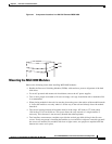
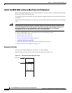
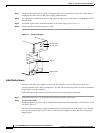
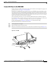
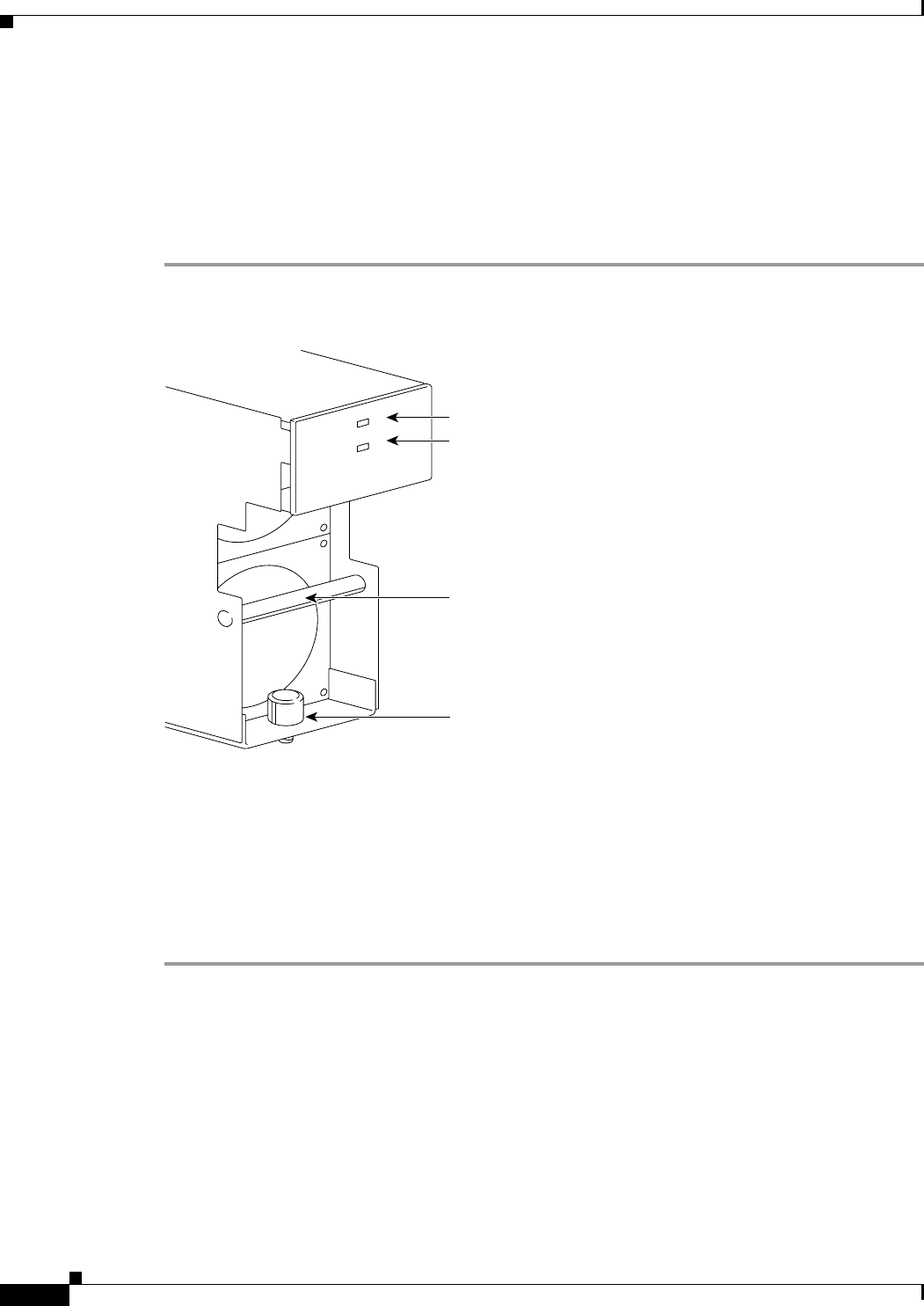
Step 4 Loosen the captive screw at the front-bottom of the power supply (see Figure 4-7).
Step 5 Grip the handle and remove the power supply.
Figure 4-7 AC Power Supply
Install the Enclosure
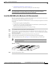
Once the cards and power supplies are removed, the enclosure can be installed in the open rack.
Use the guidelines in the “Rack Configuration” and the “Module Stacking Order” sections to determine
the placement of each component.
Follow the steps in this section for specific instructions for each type of component.
Step 1 Attach the brackets for a 23-inch rack to the enclosure modules, if necessary.
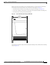
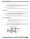
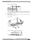
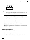
Step 2 AC-powered system
Install the optional AC power tray. Its height is three rack-mount units (three RUs is 5.25 inches or 13.34
cm). See Figure 4-8.
For a mid-mount installation, insert each mounting screw from the inside of the power tray so that the
nut is on the outside of the tray. This allows room for power supplies in either the first or last power
supply trough.
AC
DC
AC okay LED
16193
1200W
Captive screw
Handle
DC okay LED