


4-19
Cisco MGX 8850 Multiservice Switch Installation and Configuration
Release 1.1.31, Part Number 78-11223-03 Rev. B0, May 2005
Chapter 4 Enclosure and Card Installation
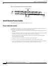
Install Electrical Connections
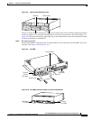
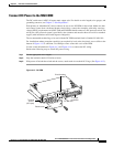
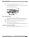
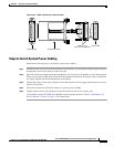
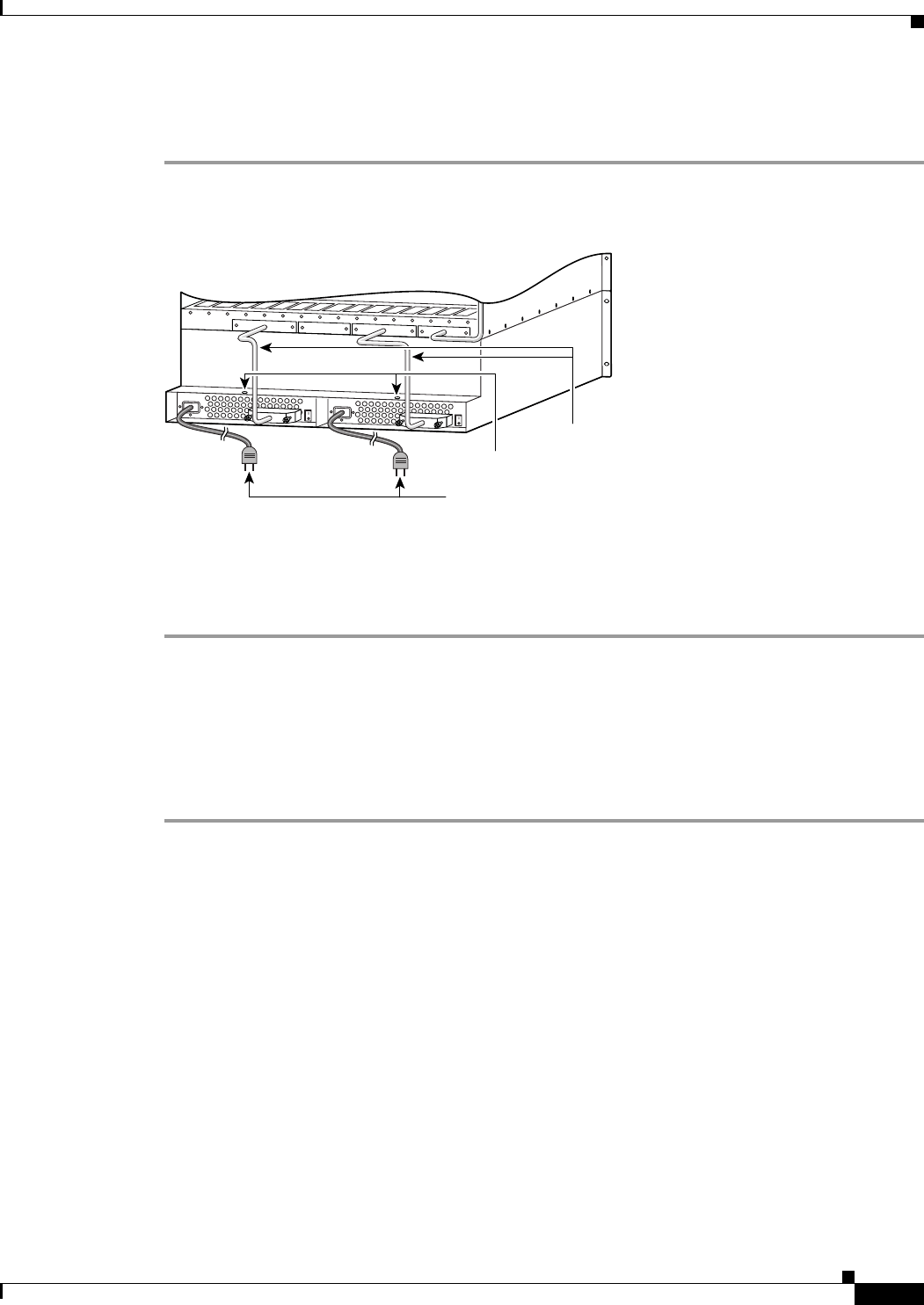
Step 4 Use a Phillips screwdriver to remove the screw at the rear of the unit (see Figure 4-16).
Step 5 Gently pull the power supply from the case toward the rear.
Figure 4-16 Removing the 110 VAC Power Supply
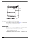
Replacing 110 VAC Power Supply
Perform the following steps to replace a 110 VAC power supply.
Step 1 Slide the power supply into a vacant position, secure the screw with a Phillips screwdriver (see
Figure 4-16).
Step 2 Connect the DC power cable to the power supply. Verify that the connectors are firmly seated.
Step 3 Secure the cable connector with the two connector screws using a Phillips screwdriver.
Step 4 Connect the AC power cable to the power supply.
Step 5 Turn the power switch on the power supply to its “On” position.
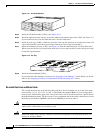
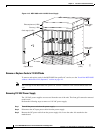
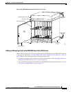
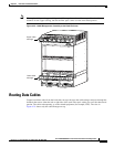
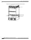
Installing the Fan Power Cable in a 110 VAC Node
After the system has been mounted, connect the fan power cable to the mother board and to the fan power
connector on the fan tray. Route the power cable as shown in Figure 4-17.
29336
Remove screws
AC power cord
DC power cable