


6-7
Cisco MGX 8850 Multiservice Switch Installation and Configuration
Release 1.1.31, Part Number 78-11223-03 Rev. B0, May 2005
Chapter 6 Card and Service Configuration
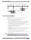
Processor Switching Module
Caution Be careful not to set multiple primaries and secondaries.
Configuration Example
For example, to configure the inband interface as the primary clock source and an external clock device
as the secondary source, enter the following commands.
Step 1 Specify the clock source.
a. For an external clock source:
popeye1r.1.8.PXM.a > cnfclksrc 7.35 S
b. For an internal clock source:
popeye1r.1.8.PXM.a > cnfclksrc 7.1 P
Step 2 To check the configuration by entering the dspclksrc command.
If you have specified an external clock source, use the CiscoView application or the CLI command
cnfextclk to select the T1 or E1 line and the impedance of the line. The syntax for cnfextclk is
cnfextclk <ClockType> <Impedance>
slot.port The parameter slot.port specifies the clock source. If a service module provides the
source, slot is the slot number of the card, and port is the number of the line that
provides the clock.
On the PXM1
• slot is 7 regardless of where the active PXM1 resides.
• port for the in-band clock is always 1.
• port for the external clock is always 35.
• port for the UNI line (stand-alone only) depends on the number of lines you have
set up on the back card.
clktyp The clock type: P for primary, S for secondary, T for tertiary, or N for null. The only
purpose of null is to remove the clock configuration that currently applies to the
specified source (slot.port).
ClockType The clock type: 1 for T1 or 2 for E1
Impedance The Impedance: 1 for 75 ohms, 2 for 100 ohms, or 3 for 120 ohms