


CHAPTER
2-1
Cisco MGX 8850 Multiservice Switch Installation and Configuration
Release 1.1.31, Part Number 78-11223-03 Rev. B0, May 2005
2
Module and Service Descriptions
This chapter includes detailed descriptions of the modules, cards and services available with the
MGX 8850:
• Processor Switching Module, page 2-1
• Service Resource Module, page 2-12
• ATM UNI Service Module (AUSM), page 2-15
• Frame Relay Service Modules, page 2-20
• Circuit Emulation Service Modules, page 2-45
• Voice Service—VISM, page 2-55
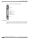
Processor Switching Module
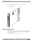
The PXM1 card set consists of the PXM1 front card, the PXM1 User Interface back card (PXM1-UI or
PXM-UI-S3), and various uplink back cards that can serve as either a trunk or a UNI.
For physical details of PXM1 cards, see Appendix A, “System Specifications.”
Caution Handle the PXM1 front card very carefully to preserve the alignment of the attached disk drive. Do
not drop or bump the PXM1.
Caution Before using the MGX 8850, verify that the daughter card on the PXM1 corresponds to the uplink
card type. Serious damage may result if the power is on and these cards are mismatched.
Note If you accidentally insert a back card for a service module into slot 7, 8, 23, or 24, carefully remove
the back card and check for bent or damaged pins on the backplane and the back card.