


2-39
Cisco MGX 8850 Multiservice Switch Installation and Configuration
Release 1.1.31, Part Number 78-11223-03 Rev. B0, May 2005
Chapter 2 Module and Service Descriptions
Frame Relay Service Modules
Illustrations
Card illustrations are shown as follows.
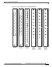
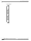
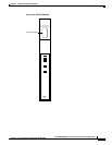
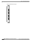
• MGX-FRSM-HS2 front card, see Figure 2-20 on page 2-41.
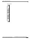
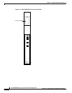
• MGX-FRSM-HS1/B front card, see Figure 2-21 on page 2-42.
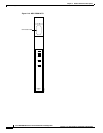
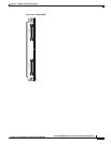
• MGX-SCSI2-2HSSI back card, see Figure 2-22 on page 2-43.
• Multifunction MGX-12IN1-4S back card, see Figure 2-23 on page 2-44. This back card supports
four V.35 or four X.21 ports.
LED Indicators
Table 2-7 and Table 2-8 describe the FRSM T1/E1 LED faceplate indicators for both the FRSM-HS1/B
and the FRSM-HS2.
MGX-FRSM-HS1/B Cabling
The cable model numbers are derived from the Cisco 12-IN-1 series of cables (see Table 2-8). Each cable
can have a male or female connector at the far end. Also, the available clock sources depend on the mode
(see Table 2-9). In DTE mode, the clock source is either line or ST (ST is a wire in the cable). For DCE,
the clock source is the front card.
See Table 2-10 for the relationship between cabling and modes and part numbers.
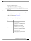
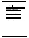
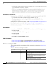
Table 2-7 Card Level LED Indicators for the FRSM-HS1/B and the FRSM-HS2
Type of LED Color Meaning
ACT Green On indicates the card set is in active mode.
STBY Yellow
• Slow blink without the active LED indicates the
card is in the boot state.
• Fast blink with the active LED indicates the card
is being downloaded.
• Fast blink indicates the service module is passing
BRAM channel information to the ASC.
• Steady yellow indicates the card is in standby
mode and the firmware is executing ADMIN code.
FAIL Red
• Steady red with active and standby LEDs off
indicates either the card is in the reset condition or
the card has failed.
• Steady red with active LED on indicates the card
was active prior to failing.
• Steady red with standby LED on indicates the card
was standby prior to failing.
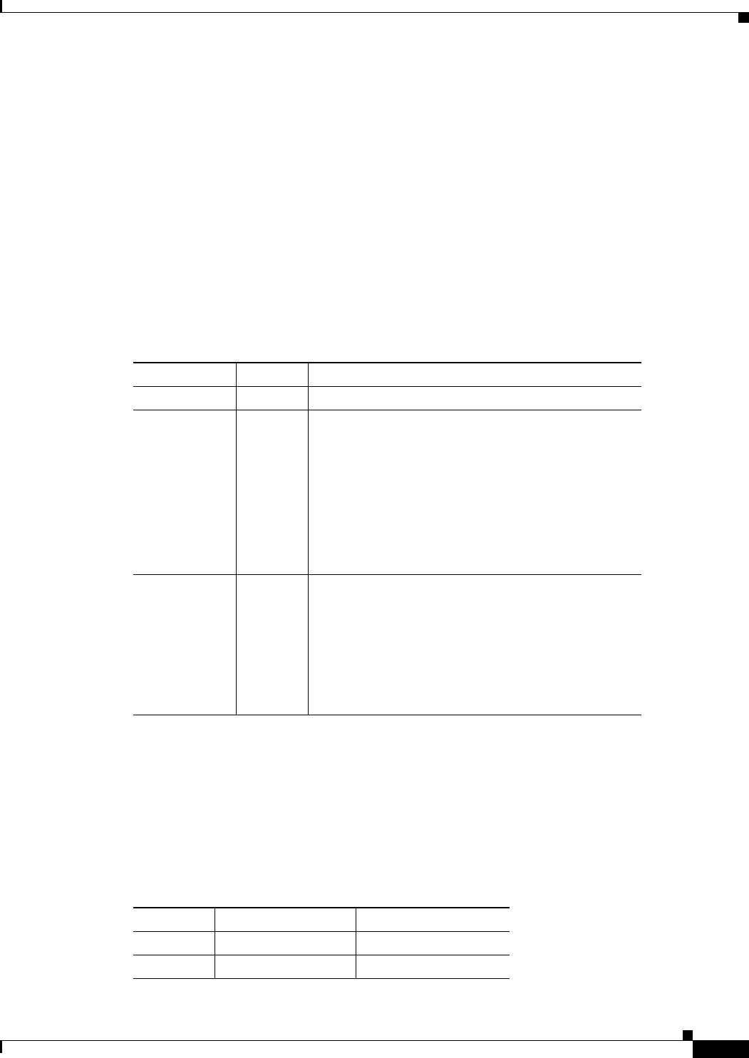
Table 2-8 12IN1-4S Back Card Cable Types
Cable Type X.21 V.35
DCE X.21 DCE V.35 DCE
DTE X.21 DTE V.35 DTE